
Clock Radio User Manual
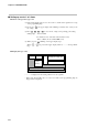
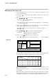
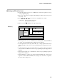
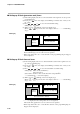
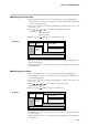
Table Of Contents
- CP-UM-5093E-04.pdf
- SAFETY PRECAUTIONS
- Contents
- Chapter 1. GENERAL
- Chapter 2. NAMES & FUNCTIONS OF PARTS
- Chapter 3. MOUNTING
- Chapter 4. WIRING
- 4-1 Wiring Precautions
- 4-2 Compensating Lead
- 4-3 Terminal Connections
- 4-4 Layout of Terminals and Recommended Lead Draw-out Direction
- 4-5 Connecting the Ground and Power Supply
- 4-6 Wiring of Standard and Add-on Terminal Base
- 4-7 Connecting Inputs (analog inputs)
- 4-8 Connecting control outputs (outputs 1, 2)
- 4-9 Connecting auxiliary outputs (outputs 2, 3)
- 4-10 Connecting Event Output (relay output)
- 4-11 Connecting Time Event Output (open-collector)
- 4-12 Connecting External Switch (RSW) Input
- 4-13 Connecting for Communications
- 4-14 Isolating Inputs and Outputs
- Chapter 5. FUNCTIONS
- Chapter 6. OPERATION
- Chapter 7. PARAMETER SETUP
- Chapter 8. PROGRAM SETUP
- Chapter 9. TROUBLESHOOTING
- Chapter 10. SPECIFICATIONS
- Chapter 11. CALIBRATION
- Index
Chapter 8. PROGRAM SETUP
8-9
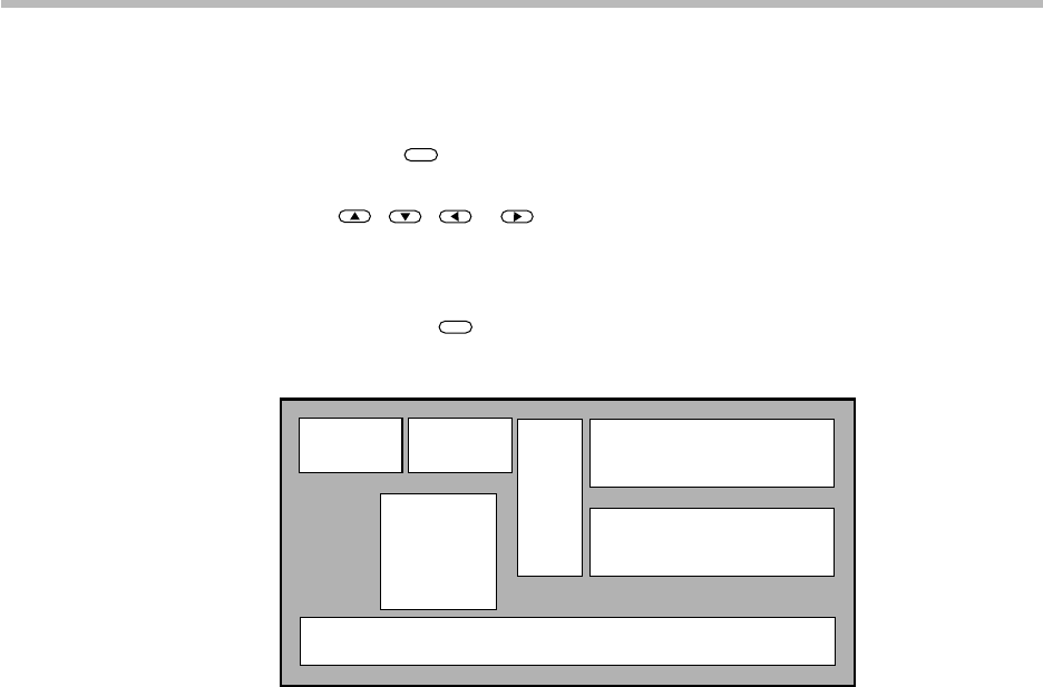
■ Setting up PID set No. items
(1) In the setting display state, move to the PID set No. items of the segment to be set up
on the programming map.
(2) If you press
ENT
, the lower display starts blinking to indicate start of entry to the
No.1 setup.
(3) Press , , or to set to the No.1 setup PID set No. setting.
Setting range: 0 to 8 (non heat/cool models)
0 to 4 (heat/cool models)
(4) When you press
ENT
, blinking on the upper display stops.
● Display
PID set No. setting value
Program No. Segment No.
Pattern
tendency
EV1 to EV3 and T1 to T5 all out
P
I
D
• When setup data C 1 1 is set to 1 and PID set auto-switching ON is selected, the PID set
No. items on the programming map are skipped and not displayed.
• On 5G output models, when setup data C 1 8 is set to 1 and programmer functions are
selected, the PID set No. items on the programming map are skipped and not dis-
played.
• On 3D output models, when setup data C 4 5 is set to 1 and 3-position-proportional
control is selected, the PID set No. items on the programming map are skipped and not
displayed.
• When setup data C 7 0 is set to 1, the PID set No. items on the programming map are all
skipped and not displayed.
• When the PID set No. setting is set to 0, this means that the PID set No. of the previous
segment is continued. When the PID set No. setting is set to 0 in the No.1 segments,
this is the same as being set to 1.