
Clock Radio User Manual
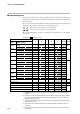
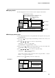
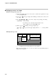
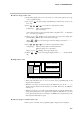
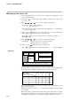
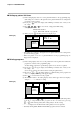
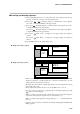
Table Of Contents
- CP-UM-5093E-04.pdf
- SAFETY PRECAUTIONS
- Contents
- Chapter 1. GENERAL
- Chapter 2. NAMES & FUNCTIONS OF PARTS
- Chapter 3. MOUNTING
- Chapter 4. WIRING
- 4-1 Wiring Precautions
- 4-2 Compensating Lead
- 4-3 Terminal Connections
- 4-4 Layout of Terminals and Recommended Lead Draw-out Direction
- 4-5 Connecting the Ground and Power Supply
- 4-6 Wiring of Standard and Add-on Terminal Base
- 4-7 Connecting Inputs (analog inputs)
- 4-8 Connecting control outputs (outputs 1, 2)
- 4-9 Connecting auxiliary outputs (outputs 2, 3)
- 4-10 Connecting Event Output (relay output)
- 4-11 Connecting Time Event Output (open-collector)
- 4-12 Connecting External Switch (RSW) Input
- 4-13 Connecting for Communications
- 4-14 Isolating Inputs and Outputs
- Chapter 5. FUNCTIONS
- Chapter 6. OPERATION
- Chapter 7. PARAMETER SETUP
- Chapter 8. PROGRAM SETUP
- Chapter 9. TROUBLESHOOTING
- Chapter 10. SPECIFICATIONS
- Chapter 11. CALIBRATION
- Index
Chapter 8. PROGRAM SETUP
8-6
■ Setting up events 1 to 3 items
● When event type is PV type event
(1) In the setting display state, move to the event 1 to 3 items of the segment to be set up
on the programming map.
(2) If you press
ENT
, the upper display starts blinking to indicate start of entry to the
No.1 setup.
(3) Press , , or to set to the No.1 setup event operating point setting.
Setting range: -1999 to 9999U
0 to 9999U (in case of absolute value deviation event)
-10.0 to 110.0% (in case of MV, MFB event)
(4) When you press
ENT
, blinking on the upper display stops.
(When
FUNC
+
CLR
are pressed, the upper display returns to “- - - -” and stops blink-
ing.)
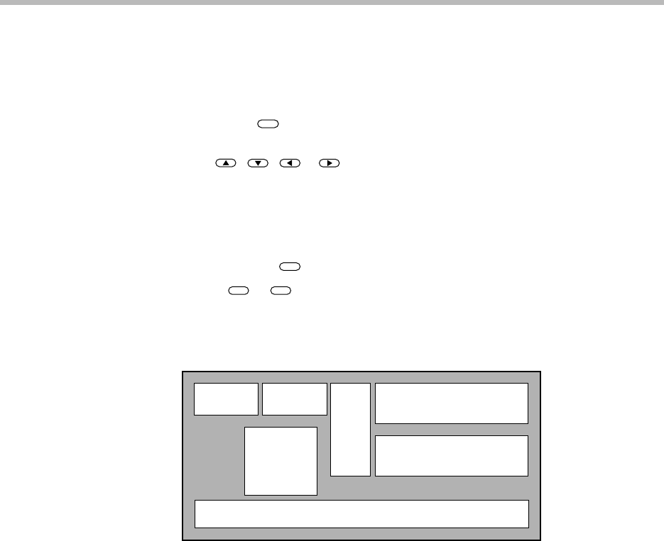
● Display (PV type event)
Operating point setting value
Program No. Segment No.
Pattern
tendency
LEDs corresponding to EV1 to EV3 lit. T1 to T5 all out
• “- - - -” is displayed for the setting values in non-set segments.
• When setup data C 6 8 is set to 1, event 1 to 3 items on the programming map are
skipped and not displayed.