
Clock Radio User Manual
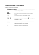
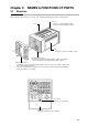
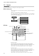
Table Of Contents
- CP-UM-5093E-04.pdf
- SAFETY PRECAUTIONS
- Contents
- Chapter 1. GENERAL
- Chapter 2. NAMES & FUNCTIONS OF PARTS
- Chapter 3. MOUNTING
- Chapter 4. WIRING
- 4-1 Wiring Precautions
- 4-2 Compensating Lead
- 4-3 Terminal Connections
- 4-4 Layout of Terminals and Recommended Lead Draw-out Direction
- 4-5 Connecting the Ground and Power Supply
- 4-6 Wiring of Standard and Add-on Terminal Base
- 4-7 Connecting Inputs (analog inputs)
- 4-8 Connecting control outputs (outputs 1, 2)
- 4-9 Connecting auxiliary outputs (outputs 2, 3)
- 4-10 Connecting Event Output (relay output)
- 4-11 Connecting Time Event Output (open-collector)
- 4-12 Connecting External Switch (RSW) Input
- 4-13 Connecting for Communications
- 4-14 Isolating Inputs and Outputs
- Chapter 5. FUNCTIONS
- Chapter 6. OPERATION
- Chapter 7. PARAMETER SETUP
- Chapter 8. PROGRAM SETUP
- Chapter 9. TROUBLESHOOTING
- Chapter 10. SPECIFICATIONS
- Chapter 11. CALIBRATION
- Index
xi
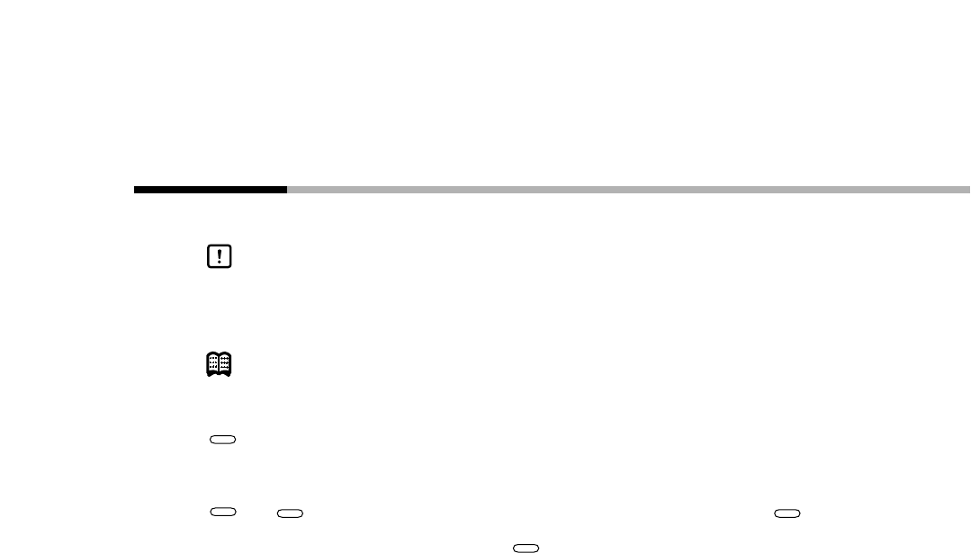
Conventions Used in This Manual
The following conventions are used in this manual.
Handling Precautions
:
Handling Precautions indicate items that the user should pay attention
to when handling the DCP301.
Note : Notes indicate useful information that the user might benefit by
knowing.
: These icons represent keys on the DCP301’s console.
+ : Combinations of icons like these indicate that must be pressed
while holding down.
(1) (2) (3) : The numbers with the parenthesis indicate steps in a sequence or
indicate corresponding parts in an explanation.
>> : Indicates the controller state after an operation.
PROG
RUN/HOLD
RUN/HOLD
PROG
DISP