
Clock Radio User Manual
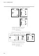
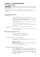
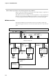
Table Of Contents
- CP-UM-5093E-04.pdf
- SAFETY PRECAUTIONS
- Contents
- Chapter 1. GENERAL
- Chapter 2. NAMES & FUNCTIONS OF PARTS
- Chapter 3. MOUNTING
- Chapter 4. WIRING
- 4-1 Wiring Precautions
- 4-2 Compensating Lead
- 4-3 Terminal Connections
- 4-4 Layout of Terminals and Recommended Lead Draw-out Direction
- 4-5 Connecting the Ground and Power Supply
- 4-6 Wiring of Standard and Add-on Terminal Base
- 4-7 Connecting Inputs (analog inputs)
- 4-8 Connecting control outputs (outputs 1, 2)
- 4-9 Connecting auxiliary outputs (outputs 2, 3)
- 4-10 Connecting Event Output (relay output)
- 4-11 Connecting Time Event Output (open-collector)
- 4-12 Connecting External Switch (RSW) Input
- 4-13 Connecting for Communications
- 4-14 Isolating Inputs and Outputs
- Chapter 5. FUNCTIONS
- Chapter 6. OPERATION
- Chapter 7. PARAMETER SETUP
- Chapter 8. PROGRAM SETUP
- Chapter 9. TROUBLESHOOTING
- Chapter 10. SPECIFICATIONS
- Chapter 11. CALIBRATION
- Index

Chapter 8. PROGRAM SETUP
8-2
● Selecting the program No. after entering program setup (continued)
When you select the program No. by this method, the display changes to segment No.1
and the pattern item on the programming map.
This method can be used, for example, to select a program No. to set up a program other
than the No. being operated in the RUN mode. It can also be used to select a program No.
to set up a program other than the currently selected No. by external switch input.
■ Mode transition
The following diagram shows the transition between modes during program setup.
The following page describes the various mode transition states (1) to (16) in the dia-
gram.
Program setup state
Basic Display State
Setting value display state
No.2 setting
entry state
PROG
FUNC
+
DISP
PROG
FUNC
+
FUNC
+
keys
keys (15)
FUNC
+
keys (12)
keys (1)
key (16)
key (2) key (3)
ENT
key (4)
ENT
key
DISP
key (11)
DISP
key (11)
DISP
key (14)
FUNC
+
keys (10)
CLR
ENT
key
FUNC
+
keys (6)
CLR
FUNC
+
keys (7)
CLR
ENT
key
ENT
(pattern item)
key (9)
(pattern item)
DISP
key (8)
ENT
key
key (5)
key (13)
Segment insertion
or deletion check
state
“ I N S .” blinking
“ d E L .” blinking
Program clear
check state
“
C L R .” blinking
No.1 setting
entry state