
Clock Radio User Manual
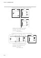
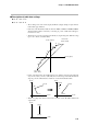
Table Of Contents
- CP-UM-5093E-04.pdf
- SAFETY PRECAUTIONS
- Contents
- Chapter 1. GENERAL
- Chapter 2. NAMES & FUNCTIONS OF PARTS
- Chapter 3. MOUNTING
- Chapter 4. WIRING
- 4-1 Wiring Precautions
- 4-2 Compensating Lead
- 4-3 Terminal Connections
- 4-4 Layout of Terminals and Recommended Lead Draw-out Direction
- 4-5 Connecting the Ground and Power Supply
- 4-6 Wiring of Standard and Add-on Terminal Base
- 4-7 Connecting Inputs (analog inputs)
- 4-8 Connecting control outputs (outputs 1, 2)
- 4-9 Connecting auxiliary outputs (outputs 2, 3)
- 4-10 Connecting Event Output (relay output)
- 4-11 Connecting Time Event Output (open-collector)
- 4-12 Connecting External Switch (RSW) Input
- 4-13 Connecting for Communications
- 4-14 Isolating Inputs and Outputs
- Chapter 5. FUNCTIONS
- Chapter 6. OPERATION
- Chapter 7. PARAMETER SETUP
- Chapter 8. PROGRAM SETUP
- Chapter 9. TROUBLESHOOTING
- Chapter 10. SPECIFICATIONS
- Chapter 11. CALIBRATION
- Index
Chapter 7. PARAMETER SETUP
7-38
(2) Turn the DCP301 ON again, and set setup data C q 0 setting to 241. For details on
how to change settings, see 7-1 Parameter Setup (page 7-1).
(3) Display the setup data C q 1 setting.
(4) Press
ENT
to display the difference (A—B) between the resistances of the Zener bar-
rier connected to leads A and B on the lower display.
(5) Press
ENT
to memorize the difference (A—B) between the resistances to the control-
ler.
(6) Press
DISP
to set the DCP301 to the basic display state.
(7) Turn the power OFF, and remove the short across A and B.
• The resistance error of the Zener barrier connected to leads A and B cannot be
adjusted unless it is 20Ω or less.
• This adjustment is not required when a Zener barrier and an input other than
an RTD are not used.
• Once the Zener barrier has been adjusted, compensation is carried out on the
Zener barrier. When using on an RTD without a Zener barrier, re-adjust without
the Zener barrier.
32
33
34
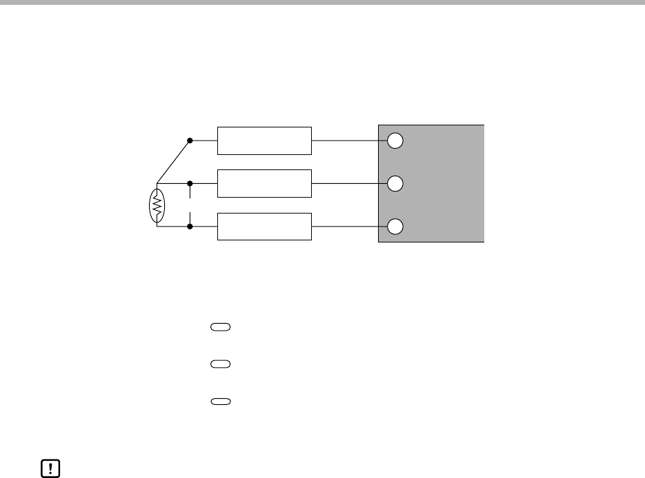
C
B
A
Zener barrier
Zener barrier
Zener barrier
DCP301
Short-circuit
● C q 1 (Input 1 Zener barrier adjustment)
The following adjustment must be made when using a Zener barrier.
(1) Turn the DCP301 OFF. When you have finished mounting and wiring the DCP301,
short-circuit across A and B on the terminals of the RTD.
Handling Precautions