
Clock Radio User Manual
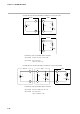
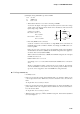
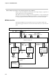
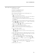
Table Of Contents
- CP-UM-5093E-04.pdf
- SAFETY PRECAUTIONS
- Contents
- Chapter 1. GENERAL
- Chapter 2. NAMES & FUNCTIONS OF PARTS
- Chapter 3. MOUNTING
- Chapter 4. WIRING
- 4-1 Wiring Precautions
- 4-2 Compensating Lead
- 4-3 Terminal Connections
- 4-4 Layout of Terminals and Recommended Lead Draw-out Direction
- 4-5 Connecting the Ground and Power Supply
- 4-6 Wiring of Standard and Add-on Terminal Base
- 4-7 Connecting Inputs (analog inputs)
- 4-8 Connecting control outputs (outputs 1, 2)
- 4-9 Connecting auxiliary outputs (outputs 2, 3)
- 4-10 Connecting Event Output (relay output)
- 4-11 Connecting Time Event Output (open-collector)
- 4-12 Connecting External Switch (RSW) Input
- 4-13 Connecting for Communications
- 4-14 Isolating Inputs and Outputs
- Chapter 5. FUNCTIONS
- Chapter 6. OPERATION
- Chapter 7. PARAMETER SETUP
- Chapter 8. PROGRAM SETUP
- Chapter 9. TROUBLESHOOTING
- Chapter 10. SPECIFICATIONS
- Chapter 11. CALIBRATION
- Index
Chapter 7. PARAMETER SETUP
7-36
(3) Equivalent circuit when N number of SSRs are connected in series
DCP301 SSR 1
IO
(VO)
VSSR'
Z
VD
SSR N
+
–
VSSR'
Z
VD
– –
+ +
Formulas (3) and (4) formulas must be satisfied.
(3) formula VSSR/MIN ≤ IO x Z + VD ≤ VO/N
(4) formula VSSR' ≤ VSSR/MAX
(VSSR' = IO x Z + VD)
(4) Equivalent circuit when N number of SSRs are connected in parallel
DCP301 SSR 1
+
–
+
–
IO
(VO)
VSSR'
Z
VD
SSR N
+
–
VSSR'
Z
VD
IO/N IO/N
Formulas (5) and (6) formulas must be satisfied.
(5) formula VSSR/MIN ≤ IO/N x Z + VD ≤ VO
(6) formula VSSR' ≤ VSSR/MAX
(VSSR' = IO/N x Z + VD)