
Clock Radio User Manual
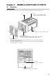
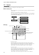
Table Of Contents
- CP-UM-5093E-04.pdf
- SAFETY PRECAUTIONS
- Contents
- Chapter 1. GENERAL
- Chapter 2. NAMES & FUNCTIONS OF PARTS
- Chapter 3. MOUNTING
- Chapter 4. WIRING
- 4-1 Wiring Precautions
- 4-2 Compensating Lead
- 4-3 Terminal Connections
- 4-4 Layout of Terminals and Recommended Lead Draw-out Direction
- 4-5 Connecting the Ground and Power Supply
- 4-6 Wiring of Standard and Add-on Terminal Base
- 4-7 Connecting Inputs (analog inputs)
- 4-8 Connecting control outputs (outputs 1, 2)
- 4-9 Connecting auxiliary outputs (outputs 2, 3)
- 4-10 Connecting Event Output (relay output)
- 4-11 Connecting Time Event Output (open-collector)
- 4-12 Connecting External Switch (RSW) Input
- 4-13 Connecting for Communications
- 4-14 Isolating Inputs and Outputs
- Chapter 5. FUNCTIONS
- Chapter 6. OPERATION
- Chapter 7. PARAMETER SETUP
- Chapter 8. PROGRAM SETUP
- Chapter 9. TROUBLESHOOTING
- Chapter 10. SPECIFICATIONS
- Chapter 11. CALIBRATION
- Index
■ Items cannot be changed by pressing , in program setup
state . . . . . . . . . . . . . . . . . . . . . . . . . . . . . . . . . . . . . . . . . . . . . . . . . . . . . . . 9-6
■ Event items cannot be changed by repeatedly pressing , in
program setup state . . . . . . . . . . . . . . . . . . . . . . . . . . . . . . . . . . . . . . . . . . 9-6
■ Time events cannot be changed by repeatedly pressing , in
program setup state . . . . . . . . . . . . . . . . . . . . . . . . . . . . . . . . . . . . . . . . . . 9-6
■ PID set items cannot be changed by repeatedly pressing , in
program setup state . . . . . . . . . . . . . . . . . . . . . . . . . . . . . . . . . . . . . . . . . 9-6
■ G.Soak items cannot be changed by repeatedly pressing , in
program setup state . . . . . . . . . . . . . . . . . . . . . . . . . . . . . . . . . . . . . . . . . . 9-6
■ PV start items, cycle items and pattern link items cannot be displayed
by repeatedly pressing , in program setup state . . . . . . . . . . . 9-6
■ Insertion/deletion of segments cannot be confirmed by pressing
+ in program setup state. . . . . . . . . . . . . . . . . . . . . . . . . . . . . . 9-7
■ Program deletion cannot be confirmed by pressing + while
entering pattern items in program setup state . . . . . . . . . . . . . . . . . . . . 9-7
■ The program cannot be copied by pressing + in the basic
display state . . . . . . . . . . . . . . . . . . . . . . . . . . . . . . . . . . . . . . . . . . . . . . . . 9-7
■ General reset is not applied by pressing + + in the basic
display state . . . . . . . . . . . . . . . . . . . . . . . . . . . . . . . . . . . . . . . . . . . . . . . . 9-7
9-3 Motor Adjustment is Impossible . . . . . . . . . . . . . . . . . . . . . . . . . . . . . . . . . . . 9-8
■ Normal wiring for direct motor rotation . . . . . . . . . . . . . . . . . . . . . . . . . . 9-9
■ Normal wiring for reverse motor rotation. . . . . . . . . . . . . . . . . . . . . . . . . 9-9
■ Alarm display caused by wrong wiring and causes . . . . . . . . . . . . . . . . 9-9
9-4 Replacing the Battery. . . . . . . . . . . . . . . . . . . . . . . . . . . . . . . . . . . . . . . . . . . 9-10
■ BAT LED blinking . . . . . . . . . . . . . . . . . . . . . . . . . . . . . . . . . . . . . . . . . . . 9-10
■ Items to prepare . . . . . . . . . . . . . . . . . . . . . . . . . . . . . . . . . . . . . . . . . . . . 9-10
■ Replacement procedure. . . . . . . . . . . . . . . . . . . . . . . . . . . . . . . . . . . . . . 9-11
Chapter 10.
SPECIFICATIONS
10-1 Specifications . . . . . . . . . . . . . . . . . . . . . . . . . . . . . . . . . . . . . . . . . . . . . . . . . 10-1
■ Accessories/option list . . . . . . . . . . . . . . . . . . . . . . . . . . . . . . . . . . . . . . 10-7
10-2 External Dimensions . . . . . . . . . . . . . . . . . . . . . . . . . . . . . . . . . . . . . . . . . . . 10-8
■ Soft dust-proof cover set. . . . . . . . . . . . . . . . . . . . . . . . . . . . . . . . . . . . . 10-9
■ Hard dust-proof cover set . . . . . . . . . . . . . . . . . . . . . . . . . . . . . . . . . . . . 10-9
■ Terminal cover set . . . . . . . . . . . . . . . . . . . . . . . . . . . . . . . . . . . . . . . . . . 10-9
Chapter 11. CALIBRATION
■ Precautions before calibration . . . . . . . . . . . . . . . . . . . . . . . . . . . . . . . . 11-1
■ Equipment needed . . . . . . . . . . . . . . . . . . . . . . . . . . . . . . . . . . . . . . . . . . 11-1
11-1 Quick Reference Table for Calibration Items. . . . . . . . . . . . . . . . . . . . . . . . 11-2
11-2 Calibration Procedures . . . . . . . . . . . . . . . . . . . . . . . . . . . . . . . . . . . . . . . . . 11-6
■ Enter calibration mode. . . . . . . . . . . . . . . . . . . . . . . . . . . . . . . . . . . . . . . 11-6
■ Function test . . . . . . . . . . . . . . . . . . . . . . . . . . . . . . . . . . . . . . . . . . . . . . 11-7
■ PV calibration. . . . . . . . . . . . . . . . . . . . . . . . . . . . . . . . . . . . . . . . . . . . . 11-10
■ Cold junction sensor calibration. . . . . . . . . . . . . . . . . . . . . . . . . . . . . . 11-12
■ Current output calibration . . . . . . . . . . . . . . . . . . . . . . . . . . . . . . . . . . 11-12
Index
DISP
CLR
FUNC
PROG
CLR
FUNC
ENT
FUNC
x