
Clock Radio User Manual
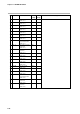
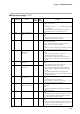
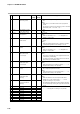
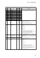
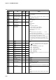
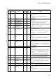
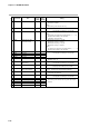
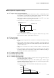
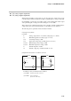
Table Of Contents
- CP-UM-5093E-04.pdf
- SAFETY PRECAUTIONS
- Contents
- Chapter 1. GENERAL
- Chapter 2. NAMES & FUNCTIONS OF PARTS
- Chapter 3. MOUNTING
- Chapter 4. WIRING
- 4-1 Wiring Precautions
- 4-2 Compensating Lead
- 4-3 Terminal Connections
- 4-4 Layout of Terminals and Recommended Lead Draw-out Direction
- 4-5 Connecting the Ground and Power Supply
- 4-6 Wiring of Standard and Add-on Terminal Base
- 4-7 Connecting Inputs (analog inputs)
- 4-8 Connecting control outputs (outputs 1, 2)
- 4-9 Connecting auxiliary outputs (outputs 2, 3)
- 4-10 Connecting Event Output (relay output)
- 4-11 Connecting Time Event Output (open-collector)
- 4-12 Connecting External Switch (RSW) Input
- 4-13 Connecting for Communications
- 4-14 Isolating Inputs and Outputs
- Chapter 5. FUNCTIONS
- Chapter 6. OPERATION
- Chapter 7. PARAMETER SETUP
- Chapter 8. PROGRAM SETUP
- Chapter 9. TROUBLESHOOTING
- Chapter 10. SPECIFICATIONS
- Chapter 11. CALIBRATION
- Index

Chapter 7. PARAMETER SETUP
7-31
No. Item Code Item Factory User Setting
Setting Setting
67 C 6 7
68 C 6 8 0
69 C 6 q 0
70 C 7 0 0
71 C 7 1 0
72 C 7 2 0
73 C 7 3 0
74 C 7 4 0
75 C 7 5 Not fixed
76 C 7 6 Not fixed
77 C 7 7 —
78 C 7 8 15
79 C 7 q 15
80 C 8 0 —
81 C 8 1 0
Alarm display
Programming item:
Events 1 to 3
Programming item:
Time events 1 to 5
Programming item:
PID set, G.Soak
Programming item:
PV start, cycle,
pattern link
Cold junction
compensation
Input operation at
input 1 disconnec-
tion
Voltage time-
proportional output
system
Output 1 selection
Output 2 selection
Unused
Voltage output 1
adjustment
Voltage output 2
adjustment
Unused
Input 1 burnout cur-
rent (expansion set-
ting 1)
0: Display ON
1: Display OFF
[Note]
Even when set to 1, alarm-related events do not
operate.
0: Display ON
1: Display OFF
[Note]
Even if each of the items are set to 1, the function
operates even if data is set to the program.
On models not supporting time events, time event
items are not displayed in program settings regardless
of the number of C 6 q settings.
0: Compensated internally
1: Compensated externally
[Note]
When the input 1 range type is other than a thermo-
couple, “– – – –” is displayed and setting is not
possible.
0: Upscale
1: Downscale
[Note]
This setting is valid when the input 1 range type is
thermocouple, resistance temperature detector or
linear (mV series).
0: Input ON again enabled within time-proportional cycle
1: Input ON again disabled within time-proportional cycle
[Note]
When both of outputs 1 and 2 are not voltage time-
proportional outputs, “– – – –” is displayed and setting
is not possible.
0: Current output
1: Voltage output
[Note]
When each of the outputs are relay output, position-
proportional output, auxiliary output or output is not
mounted, “– – – –” is displayed and setting is not
possible.
Factory setting is 1 if outputs are voltage output
according to output type. Otherwise, the setting is 0.
[Note]
“– – – –” is displayed and setting is not possible.
2 to 22mA
[Note]
When each of the outputs are other than voltage output,
“– – – –” is displayed and setting is not possible.
Normally, use the factory setting.
[Note]
“– – – –” is displayed and setting is not possible.
0: Burnout current ON
1: Burnout current OFF
[Note]
Normally set to 0.
Set to 1 when infra-red thermocouple RT50 is connected
to input 1.