
Clock Radio User Manual
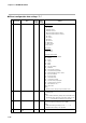
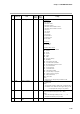
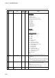
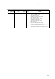
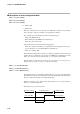
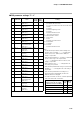
Table Of Contents
- CP-UM-5093E-04.pdf
- SAFETY PRECAUTIONS
- Contents
- Chapter 1. GENERAL
- Chapter 2. NAMES & FUNCTIONS OF PARTS
- Chapter 3. MOUNTING
- Chapter 4. WIRING
- 4-1 Wiring Precautions
- 4-2 Compensating Lead
- 4-3 Terminal Connections
- 4-4 Layout of Terminals and Recommended Lead Draw-out Direction
- 4-5 Connecting the Ground and Power Supply
- 4-6 Wiring of Standard and Add-on Terminal Base
- 4-7 Connecting Inputs (analog inputs)
- 4-8 Connecting control outputs (outputs 1, 2)
- 4-9 Connecting auxiliary outputs (outputs 2, 3)
- 4-10 Connecting Event Output (relay output)
- 4-11 Connecting Time Event Output (open-collector)
- 4-12 Connecting External Switch (RSW) Input
- 4-13 Connecting for Communications
- 4-14 Isolating Inputs and Outputs
- Chapter 5. FUNCTIONS
- Chapter 6. OPERATION
- Chapter 7. PARAMETER SETUP
- Chapter 8. PROGRAM SETUP
- Chapter 9. TROUBLESHOOTING
- Chapter 10. SPECIFICATIONS
- Chapter 11. CALIBRATION
- Index
Chapter 7. PARAMETER SETUP
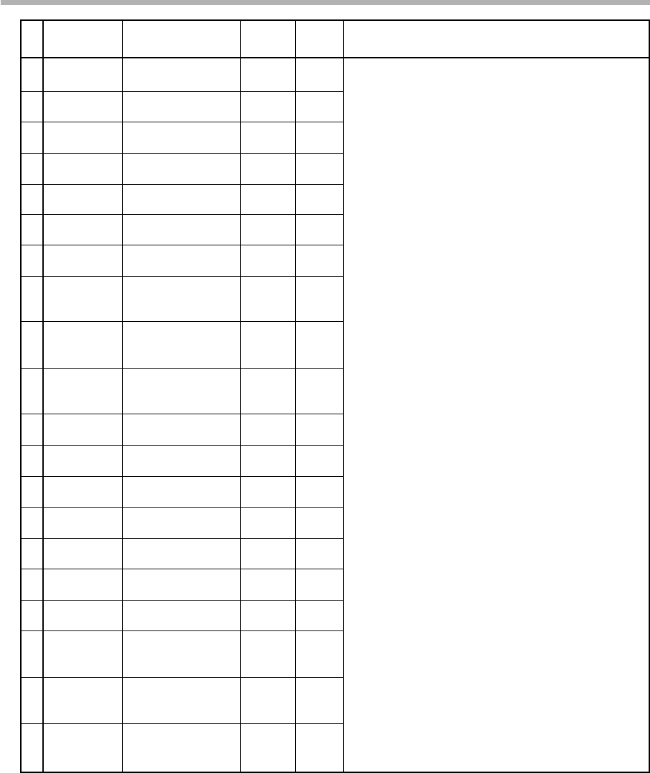
7-25
No. Item Code Item Factory User Setting
Setting Setting
41 P -5 100.0
42 1 -5 0
43 D -5 0
44 O L -5 0.0
45 O H -5 100.0
46 R E -5 50.0
47 B R -5 0
48 D P -5 100.0
49 D 1 -5 120
50 D D -5 0
51 P -6 100.0
52 1 -6 0
53 D -6 0
54 O L -6 0.0
55 O H -6 100.0
56 R E -6 50.0
57 B R -6 0
58 D P -6 100.0
59 D 1 -6 120
60 D D -6 0
Proportional band
(PID set 5)
Reset time
(PID set 5)
Rate time
(PID set 5)
MV lower limit
(PID set 5)
MV upper limit
(PID set 5)
Manual reset
(PID set 5)
Brake
(PID set 5)
Disturbance inhibit
proportional band
(PID set 5)
Disturbance inhibit
reset time
(PID set 5)
Disturbance inhibit
rate time
(PID set 5)
Proportional band
(PID set 6)
Reset time
(PID set 6)
Rate time
(PID set 6)
MV lower limit
(PID set 6)
MV upper limit
(PID set 6)
Manual reset
(PID set 6)
Brake
(PID set 6)
Disturbance inhibit
proportional band
(PID set 6)
Disturbance inhibit
reset time
(PID set 6)
Disturbance inhibit
rate time
(PID set 6)