
Clock Radio User Manual
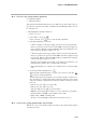
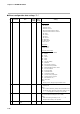
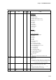
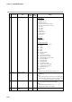
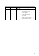
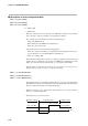
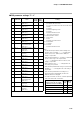
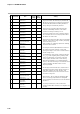
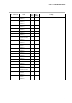
Table Of Contents
- CP-UM-5093E-04.pdf
- SAFETY PRECAUTIONS
- Contents
- Chapter 1. GENERAL
- Chapter 2. NAMES & FUNCTIONS OF PARTS
- Chapter 3. MOUNTING
- Chapter 4. WIRING
- 4-1 Wiring Precautions
- 4-2 Compensating Lead
- 4-3 Terminal Connections
- 4-4 Layout of Terminals and Recommended Lead Draw-out Direction
- 4-5 Connecting the Ground and Power Supply
- 4-6 Wiring of Standard and Add-on Terminal Base
- 4-7 Connecting Inputs (analog inputs)
- 4-8 Connecting control outputs (outputs 1, 2)
- 4-9 Connecting auxiliary outputs (outputs 2, 3)
- 4-10 Connecting Event Output (relay output)
- 4-11 Connecting Time Event Output (open-collector)
- 4-12 Connecting External Switch (RSW) Input
- 4-13 Connecting for Communications
- 4-14 Isolating Inputs and Outputs
- Chapter 5. FUNCTIONS
- Chapter 6. OPERATION
- Chapter 7. PARAMETER SETUP
- Chapter 8. PROGRAM SETUP
- Chapter 9. TROUBLESHOOTING
- Chapter 10. SPECIFICATIONS
- Chapter 11. CALIBRATION
- Index
Chapter 7. PARAMETER SETUP
7-22
■ Description of event configuration data
● E D 1 (event 1 standby)
● E D 2 (event 2 standby)
● E D 3 (event 3 standby)
0: Standby OFF
1: Standby ON
• When set to standby ON, event output becomes OFF if the controller is in the standby
state even if the condition for turning event output ON is satisfied.
• The controller enters the standby state in the following instances:
- When in the READY mode
- When shifting from the READY to the RUN mode
- When the power is turned ON
• The standby state is canceled in the following instances:
- When the condition for turning event output OFF (not including the hysteresis pe-
riod) is satisfied in one of the RUN, HOLD or FAST modes
- When set to standby OFF
• In the following example, PV event direct, operating point 500°C, hysteresis 10°C and
standby ON are set. When the mode changes from READY to the RUN mode at PV
550°C, the controller enters the standby state, so event output is turned OFF.
• Standby functions only when the event type is set to PV type event, and does not
function when set to time event type or controller status type.
● D L 1 (event 1 ON delay time)
● D L 2 (event 2 ON delay time)
● D L 3 (event 3 ON delay time)
• The ON delay time is processed after completing all processes up to event output standby
ON/OFF. Event output is turned ON when more than the ON delay time has elapsed
with the condition for turning event output ON satisfied.
• When the event type is set to ADV, the ON delay function does not operate whatever
value is set as the ON delay time.
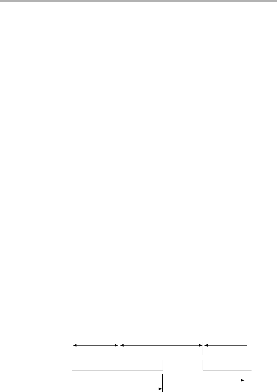
• ON delay time is processed as follows.
ON delay time
Event ON conditions
Event output ON
Event OFF conditions
Event output OFF
Time
Event output OFF
Event OFF conditions