
Clock Radio User Manual
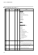
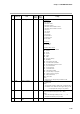
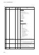
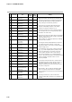
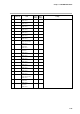
Table Of Contents
- CP-UM-5093E-04.pdf
- SAFETY PRECAUTIONS
- Contents
- Chapter 1. GENERAL
- Chapter 2. NAMES & FUNCTIONS OF PARTS
- Chapter 3. MOUNTING
- Chapter 4. WIRING
- 4-1 Wiring Precautions
- 4-2 Compensating Lead
- 4-3 Terminal Connections
- 4-4 Layout of Terminals and Recommended Lead Draw-out Direction
- 4-5 Connecting the Ground and Power Supply
- 4-6 Wiring of Standard and Add-on Terminal Base
- 4-7 Connecting Inputs (analog inputs)
- 4-8 Connecting control outputs (outputs 1, 2)
- 4-9 Connecting auxiliary outputs (outputs 2, 3)
- 4-10 Connecting Event Output (relay output)
- 4-11 Connecting Time Event Output (open-collector)
- 4-12 Connecting External Switch (RSW) Input
- 4-13 Connecting for Communications
- 4-14 Isolating Inputs and Outputs
- Chapter 5. FUNCTIONS
- Chapter 6. OPERATION
- Chapter 7. PARAMETER SETUP
- Chapter 8. PROGRAM SETUP
- Chapter 9. TROUBLESHOOTING
- Chapter 10. SPECIFICATIONS
- Chapter 11. CALIBRATION
- Index

Chapter 7. PARAMETER SETUP
7-21
No. Item Code Item Factory User Setting
Setting Setting
13 T T 0 0: T1 to T5 are all time events.
1: T1 is a segment No. event.
T2 to T5 are time events.
2: T1 and T2 are segment No. events.
T3 to T5 are time events.
3: T1 to T3 are segment No. events.
T4 and T5 are time events.
4: T1 to T4 are segment No. events.
T5 is a time event.
5: All T1 to T5 are segment No. events.
[Note]
On models not supporting time events, “– – – –” is
displayed and setting is not possible.
Settings can be changed only in the READY mode.
Time event type