
Clock Radio User Manual
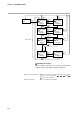
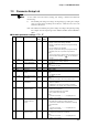

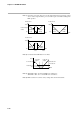
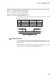
Table Of Contents
- CP-UM-5093E-04.pdf
- SAFETY PRECAUTIONS
- Contents
- Chapter 1. GENERAL
- Chapter 2. NAMES & FUNCTIONS OF PARTS
- Chapter 3. MOUNTING
- Chapter 4. WIRING
- 4-1 Wiring Precautions
- 4-2 Compensating Lead
- 4-3 Terminal Connections
- 4-4 Layout of Terminals and Recommended Lead Draw-out Direction
- 4-5 Connecting the Ground and Power Supply
- 4-6 Wiring of Standard and Add-on Terminal Base
- 4-7 Connecting Inputs (analog inputs)
- 4-8 Connecting control outputs (outputs 1, 2)
- 4-9 Connecting auxiliary outputs (outputs 2, 3)
- 4-10 Connecting Event Output (relay output)
- 4-11 Connecting Time Event Output (open-collector)
- 4-12 Connecting External Switch (RSW) Input
- 4-13 Connecting for Communications
- 4-14 Isolating Inputs and Outputs
- Chapter 5. FUNCTIONS
- Chapter 6. OPERATION
- Chapter 7. PARAMETER SETUP
- Chapter 8. PROGRAM SETUP
- Chapter 9. TROUBLESHOOTING
- Chapter 10. SPECIFICATIONS
- Chapter 11. CALIBRATION
- Index
Chapter 7. PARAMETER SETUP
7-15
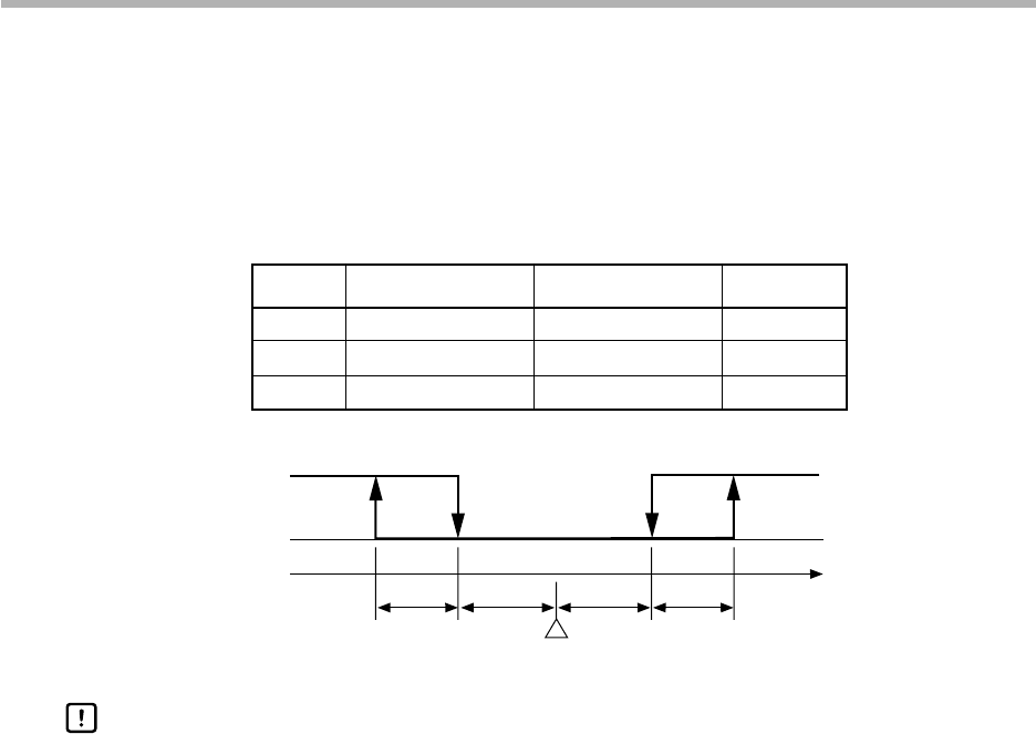
● D v -L (3-position control deviation lower limit)
● D v -H (3-position control deviation upper limit)
● H Y -L (3-position control lower limit hysteresis)
● H Y -H (3-position control upper limit hysteresis)
In 3-position control, control is carried out in the following three states in the RUN,
HOLD, FAST and END modes.
State Heat-side Output Cool-side Output MV
1 OFF (0.0%) ON (100.0%) 0.0%
2 OFF (0.0%) OFF (0.0%) 50.0%
3 ON (100.0%) OFF (0.0%) 100.0%
SP
PV
OFF
ON
OFF
ON
Output (heat) Output (cool)
HY-L DV-L DV-H HY-H
Even in 3-position control, output is time-proportional in the READY mode. This
is set in setup data C 1 6 (MV (heat) in READY mode) and C 1 7 (MV (cool) in
READY mode).
When connecting an actuator that may burn by time-proportional output, set setup
data C 1 6 and C 1 7 so that output in the READY mode is 0%.
Handling Precautions