DCP301 Digital Program Controller User’s Manual EN1I-6197 Issue 7 (02/04)
WARRANTY The Honeywell device described herein has been manufactured and tested for corrent operation and is warranted for a period of one year. TECHNICAL ASSISTANCE If you encounter a problem with your unit, please review all the configuration data to verify that your selections are consistent with your application; (i.e. Inputs, Outputs, Alarms, Limits, etc.). If the problem persists after checking the above parameters, you can get technical assistance by calling the following: In the U.S.A.
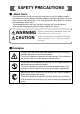
SAFETY PRECAUTIONS ■ About Icons Safety precautions are for ensuring safe and correct use of this product, and for preventing injury to the operator and other people or damage to property. You must observe these safety precautions. The safety precautions described in this manual are indicated by various icons. The following describes the icons and their meanings. Be sure to read and understand the following descriptions before reading this manual.
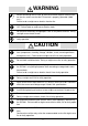
WARNING Before connecting the DCP301 to the measurement target or external control circuits, make sure that the FG terminal is properly grounded (100Ω max.). Failure to do so might cause electric shock or fire. Before wiring, or removing/mounting the DCP301, be sure to turn the power OFF. Failure to do so might cause electric shock. Do not touch electrically charged parts such as the power terminals. Doing so might cause electric shock. Do not disassemble the DCP301.
CAUTION Use induced lighting surge preventive device if there is the risk of power surges caused by lightning. Failure to do might cause fire or faulty operation. Before replacing the battery, be sure to turn the power OFF. Failure to do so might cause electric shock. Do not touch internal components immediately after turning the power OFF to replace the battery. Doing so might cause burns. ・ Do not insert the battery with the polarities (+,-) reversed.
Unpacking Check the following when removing the DCP301 from its package. 1. Check the model No. to make sure that you have received the product that you ordered. 2. Check the DCP301 for any apparent physical damage. 3. Check the contents of the package against the Package List to make sure that all accessories are included in the package. After unpacking, handle the DCP301 and its accessories taking care to prevent damage or loss of parts.
Organization of This User’s Manual This manual is organized as follows. Chapter 1. GENERAL This chapter describes DCP301 applications, features and basic function blocks. It also gives a list of model numbers. Chapter 2. NAMES & FUNCTIONS OF PARTS This chapter describes the names and functions of DCP301 parts, input types and range Nos. Chapter 3. MOUNTING This chapter describes how to mount the DCP301 on control panels. This chapter is required reading for designers of control systems using the DCP301.
Contents Safety Precautions Unpacking Request Organization of the Product Manual Conventions Used in This Manual Chapter 1. GENERAL 1-1 1-2 1-3 1-4 Features . . . . . . . . . . . . . . . . . . . . . . . . . . . . . . . . . . . . . . . . . . . . . . . . . . . . . . . 1-1 Basic Function Blocks . . . . . . . . . . . . . . . . . . . . . . . . . . . . . . . . . . . . . . . . . . . 1-2 Data Structure . . . . . . . . . . . . . . . . . . . . . . . . . . . . . . . . . . . . . . . . . . . . . . . . . .
4-7 Connecting Inputs (analog inputs) . . . . . . . . . . . . . . . . . . . . . . . . . . . . . . . . . 4-8 ■ Connecting input 1 . . . . . . . . . . . . . . . . . . . . . . . . . . . . . . . . . . . . . . . . . . . 4-8 4-8 Connecting control outputs (outputs 1, 2) . . . . . . . . . . . . . . . . . . . . . . . . . . . 4-9 ■ Relay output (0D) . . . . . . . . . . . . . . . . . . . . . . . . . . . . . . . . . . . . . . . . . . . . 4-9 ■ Current output (5G) . . . . . . . . . . . . . . . . . . . . . . . . . . . .
■ Display in program operation mode . . . . . . . . . . . . . . . . . . . . . . . . . . . . . 6-3 ■ Display in constant-value operation mode . . . . . . . . . . . . . . . . . . . . . . . 6-5 6-3 Program Selection . . . . . . . . . . . . . . . . . . . . . . . . . . . . . . . . . . . . . . . . . . . . . . 6-7 ■ How to select the program No. . . . . . . . . . . . . . . . . . . . . . . . . . . . . . . . . . 6-7 6-4 External Switch (RSW) Operations . . . . . . . . . . . . . . . . . . . . . . . . . . . . . . . .
8-2 Copying Programs . . . . . . . . . . . . . . . . . . . . . . . . . . . . . . . . . . . . . . . . . . . . . 8-14 ■ Operation. . . . . . . . . . . . . . . . . . . . . . . . . . . . . . . . . . . . . . . . . . . . . . . . . . 8-14 8-3 General Reset . . . . . . . . . . . . . . . . . . . . . . . . . . . . . . . . . . . . . . . . . . . . . . . . . 8-15 ■ Operation. . . . . . . . . . . . . . . . . . . . . . . . . . . . . . . . . . . . . . . . . . . . . . . . . . 8-15 Chapter 9.
■ Items cannot be changed by pressing , in program setup state . . . . . . . . . . . . . . . . . . . . . . . . . . . . . . . . . . . . . . . . . . . . . . . . . . . . . . . 9-6 ■ Event items cannot be changed by repeatedly pressing , in program setup state . . . . . . . . . . . . . . . . . . . . . . . . . . . . . . . . . . . . . . . . . . 9-6 ■ Time events cannot be changed by repeatedly pressing , in program setup state . . . . . . . . . . . . . . . . . . . . . . . . . . . . . . . . . . . . . . . . . .
Conventions Used in This Manual The following conventions are used in this manual. Handling Precautions : Handling Precautions indicate items that the user should pay attention to when handling the DCP301. Note : Notes indicate useful information that the user might benefit by knowing. DISP PROG : These icons represent keys on the DCP301’s console. + RUN/HOLD : Combinations of icons like these indicate that while holding (1) (2) (3) PROG RUN/HOLD down.
Chapter 1. GENERAL Chapter 1. GENERAL 1-1 Features The DCP301 is a general-purpose single-loop program controller for controlling temperature, pressure, flow rate and other inputs. ● High accuracy achieved by multi-range input Multi-range input allows you to choose between the following input types: thermocouple, resistance temperature detector (RTD), dc voltage and dc current. Accuracy of ±0.1%FS±1 digit and a sampling cycle of 0.1s ensures consistently high-precision control.
Chapter 1.
Chapter 1. GENERAL 1-3 Data Structure Data is made up of “parameters” that are used mainly for setting controller functions and “programs” that are used for setting operation during program operation of the controller. • Total of 19 program patterns Program No.=19 Number of segments=8 (3) SP (2) (4) (5) (6) Program No.=3 Number of segments=15 SP Program No.=2 Number of segments=19 Program No.
Chapter 1. GENERAL 1-4 System Configuration ■ System configuration by CPL communications On DCP301 models supporting RS-485 communications (optional), controllers can be connected as slave stations on a communications network.
Chapter 1. GENERAL 1-5 Model Numbers ■ Model selection guide Basic Model No.
Chapter 2. NAMES & FUNCTIONS OF PARTS Chapter 2. NAMES & FUNCTIONS OF PARTS 2-1 Structure This controller comprises a body, console, case, standard terminal base and add-on terminal base. Case Console Contains 7-segment display, LEDs, operation keys and loader connector. Body Contains console and electrical circuits.
Chapter 2. NAMES & FUNCTIONS OF PARTS 2-2 Console The console comprises keys for operating the controller, displays and LEDs. ■ Basic display state The “basic display state” is the state in which the controller operating state is displayed on the console. When the power is turned ON, the controller is in this state. Key operation changes the controller from the basic display state to one of the parameter setup, program setup, program copy or general reset states.
Chapter 2. NAMES & FUNCTIONS OF PARTS • Mode indicator LEDs RUN, HLD : Display the READY, RUN, HOLD, FAST and END modes. (See following table.) Mode LED RUN HLD MAN PRG READY RUN HOLD FAST END Out Lit Out Blinking Out Out Out Lit Out Blinking : Lights in the MANUAL mode, and goes out in the AUTO mode. : Lights in the program setup state. Otherwise, this LED is out. • Upper display In the basic display state, displays PV and other values.
Chapter 2. NAMES & FUNCTIONS OF PARTS ■ Keys PROG FUNC DISP : Program key : Display key : Function key : Left arrow key, right arrow key : Up arrow key, down arrow key Loader jack A/M : Auto/Manual key AT : Auto-tuning key RUN/HOLD CLR PARA : Run/Hold key : Clear key : Parameter key ENT : Enter key Category Basic display state Function Key operation To change the display DISP To change the program No.
Chapter 2. NAMES & FUNCTIONS OF PARTS Category Function Parameter setup Starts parameter setup. So the controller enters selection of setup group (major item).
Chapter 2. NAMES & FUNCTIONS OF PARTS Category Program copy Function Key operation To start program copy (in basic display state) PROG + To change the copy destination program No.
Chapter 2. NAMES & FUNCTIONS OF PARTS ■ Functions using two or more keys PROG + RUN/HOLD : Reset keys Press RUN/HOLD with PROG held down in the basic display state to reset the controller. The controller enters the READY mode in the RUN, HOLD, FAST or END modes. The controller cannot be reset in the READY mode by key operation. PROG + DISP : Advance keys Press DISP with PROG held down in the program operation mode in the basic display state to advance the program.
Chapter 2. NAMES & FUNCTIONS OF PARTS 2-3 Input Type and Range No. ■ Inputs ● Thermocouple Input Format Range No. Code Temp. Range (°C) Temp. Range (°F) K (CA) 0 K09 0 to 1200 0 to 2400 K (CA) 1 K08 0.0 to 800.0 0 to 1600 K (CA) 2 K04 0.0 to 400.0 K (CA) 3 K29 -200 to 1200 -300 to 2400 K (CA) 4 K44 -200.0 to 300.0 -300 to 700 K (CA) 5 K46 -200.0 to 200.0 -300 to 400 E (CRC) 6 E08 0.0 to 800.0 0 to 1800 J (IC) 7 J08 0.0 to 800.0 0 to 1600 T (CC) 8 T44 -200.
Chapter 2. NAMES & FUNCTIONS OF PARTS ● dc current, dc voltage Input Format Range No. Code 4 to 20mA 64 C01 0 to 20mA 65 C08 0 to 10mA 66 M01 -10 to +10mV 67 L02 0 to 100mV 68 L01 0 to 1V 69 L04 -1 to +1V 70 L08 1 to 5V 71 V01 0 to 5V 72 L05 0 to 10V 73 L07 Range (programmable) -1999 to 9999 Handling Precautions • The unit of code Z06 is Kelvin (K) • The lower limit readout of code B18 is 20°C (68°F).
Chapter 3. MOUNTING Chapter 3. MOUNTING External Dimensions Unit: mm (18) 159.5 15 137 96 A B A B (106x104) 96 Mounting bracket 81405411-001 Soft dust-proof cover set (sold separately) 81446087-001 Hard dust-proof cover set (sold separately) 81446083-001 Terminal cover set (sold separately) 81446084-001 110.5 B-B 90.2 A-A 91.5 3-1 Terminal screw 37 78.
Chapter 3. MOUNTING 3-2 Panel Cutout Dimensions Use a steel panel of at least 2mm in thickness for mounting the controller. Panel cutout dimensions during multiple mounted (recommended) 92+0.8 0 92+0.8 0 Panel cutout dimensions Unit: mm 92+0.8 0 46 96 x (N - 1) 46 96 x N - 4 N=number of units installed Panel cutout dimensions when mounting units horizontally and vertically (recommended) 150min.(when vertically mounted) 99 min. (when horizontally mounted) (107 min.
Chapter 3. MOUNTING 3-3 Mounting WARNING Before wiring, or removing/mounting the DCP301, be sure to turn the power OFF. Failure to do so might cause electric shock. Do not disassemble the DCP301. Doing so might cause electric shock or faulty operation. CAUTION Use the DCP301 within the operating ranges recommended in the specifications (temperature, humidity, voltage, vibration, shock, mounting direction, atmosphere, etc.). Failure to do so might cause fire or faulty operation.
Chapter 3. MOUNTING ■ Noise generating sources and countermeasures • Generally, the following generate electrical noise: (1) Relays and contacts (2) Solenoid coils, solenoid valves (3) Power lines (in particular, 90Vac min.
Chapter 3. MOUNTING ■ Mounting method Panel Mounting bracket 81405411-001 Mounting bracket • Firmly secure the top and bottom of the controller by the mounting brackets. • When mounting the controller, secure by lower mounting bracket (1) first. (2) Mounting bracket Panel Panel (1) Handling Precautions To secure the controller, tighten the screw on the mounting bracket (supplied) until there is no more play and then tighten a further full turn. Take care not to overtighten the screw.
Chapter 4. WIRING Chapter 4. WIRING 4-1 Wiring Precautions WARNING Before connecting the DCP301 to the measurement target or external control circuits, make sure that the FG terminal is properly grounded (100Ω max.). Failure to do so might cause electric shock or fire. Before wiring, or removing/mounting the DCP301, be sure to turn the power OFF. Failure to do so might cause electric shock. Do not touch electrically charged parts such as the power terminals. Doing so might cause electric shock.
Handling Precautions • Before wiring the DCP301, check the controller catalog No. and terminal Nos. on the label on the rear of the body. After wiring the DCP301, be sure to check the wiring for any mistakes. • Maintain a distance of at least 50cm between I/O leads or communications leads and the power lead. Also, do not pass these leads through the same piping or wiring duct. • When wiring with crimped terminals, take care to prevent contact with adjacent terminals.
Chapter 4. WIRING 4-2 Compensating Lead In the case of thermocouple input, connect the bare thermocouple lead to the terminal. If the thermocouple is located a long way from the DCP301 or the thermocouple is connected to a terminal, extend the connection using a compensating lead and then connect to the terminal. Use shielded compensating leads only. • For I/O other than thermocouples, use JCS-364 shielded instrument polyethylene insulated vinyl sheath cable or equivalent product.
Chapter 4. WIRING 4-3 Terminal Connections Use crimped terminals that fit onto M3.5 screws. 7.3 max. 7.4 Unit: mm 6.6 max. 3.7dia. Handling Precautions • When installing the DCP301 in locations subject to vibration or impact, be sure to use round crimped terminals to prevent the lead from coming loose from the terminal. • When wiring with crimped terminals, take care to prevent contact with adjacent terminals. • The recommended tightening torque for the terminal screws is 0.78 to 0.98N•m.
Chapter 4. WIRING 4-4 Layout of Terminals and Recommended Lead Draw-out Direction Wiring is carried out on the standard terminal base or add-on terminal base. The following diagram shows the recommended draw-out directions for the leads on the standard terminal base. The lead draw-out directions are the same when using the add-on terminal base.
Chapter 4. WIRING 4-5 Connecting the Ground and Power Supply ■ Power supply Connect the DCP301 to a single-phase power supply for controllers, and take measures to prevent the influence of electrical noise.
Chapter 4.
Chapter 4. WIRING 4-7 Connecting Inputs (analog inputs) ■ Connecting input 1 Multiple input 1 supports various sensor inputs. Connect as follows according to the sensor being used. • Thermocouple input • RTD input 31 31 32 32 33 33 B 34 34 A • dc voltage input C • dc current input 31 31 32 32 33 mA 33 V, mV 34 34 Handling Precautions • Applying voltage across dc current input terminals (31) and (33) may cause faulty operation. • Take care of polarities (+,-) when wiring inputs.
Chapter 4. WIRING 4-8 Connecting control outputs (outputs 1, 2) WARNING Before wiring, or removing/mounting the DCP301, be sure to turn the power OFF. Failure to do so might cause electric shock. ■ Relay output (0D) Connect as follows.
Chapter 4. WIRING ■ Voltage output (6D) Connect as follows. 11 SSR 12 2 to 22mAdc With current adjustment function (setup: C 7 8 ) 13 Handling Precautions Voltage output is reliant on an internal fixed-current circuit. Set the current value in the setup data so that the optimum voltage is obtained matched to the conditions of the SSR in use and load. Factory setting: general-purpose SSR voltage value. ■ Heat/cool output (3D) Connect as follows.
Chapter 4. WIRING 4-9 Connecting auxiliary outputs (outputs 2, 3) Optional auxiliary outputs can be added on. WARNING Before wiring, or removing/mounting the DCP301, be sure to turn the power OFF. Failure to do so might cause electric shock. ■ 0D, 5G, 6D auxiliary outputs 14 Receiver 15 16 17 Receiver 18 19 Auxiliary output 1 (output 2) 4 to 20/0 to 20mAdc Resistive load 600Ω max. Auxiliary output 2 (output 3) 4 to 20/0 to 20mAdc Resistive load 600Ω max.
Chapter 4. WIRING 4-10 Connecting Event Output (relay output) Event outputs EV1 and EV2 are 1a contact, and event output EV3 is 1a1b. Event outputs are connected on the standard terminal base.
Chapter 4. WIRING 4-11 Connecting Time Event Output (open-collector) Optional time event outputs T1 to T5 (open-collector outputs) can be added on. Time event outputs are connected on the add-on terminal base. Add-on terminal base T1 Load 49 T2 Load 50 T3 Load Maximum load current: 70mA/load OFF leakage current: 0.1mA max.
Chapter 4. WIRING 4-12 Connecting External Switch (RSW) Input The DCP301 is provided with four external switch inputs as standard (eight optional). The optional eight inputs are located on the add-on terminal base. Wire the external switch inputs across the standard and add-on terminal bases.
Chapter 4.
Chapter 4. WIRING 4-13 Connecting for Communications Some controller models support the RS-485 communications interface. Select the RS-485 communications models by selected the required catalog No. Connect as follows. Handling Precautions The DCP301 operates as a slave station. ■ RS-485 interface Add-on terminal base 57 58 59 60 61 SDA SDB RDA RDB SG Handling Precautions • Multi-drop connection of slave stations is possible. • Make sure that different addresses are set for each slave station.
Chapter 4. WIRING ● 5-wire system RS-485 mutual connection Terminating resistor Slave station DCP301 57 Terminating resistor 58 59 60 61 SDA SDB RDA RDB SG FG Shielded cable Master station RDA RDB SDA SDB SG FG Shielded cable Slave station DCP301 57 58 59 Handling Precautions Be sure to connect SG terminals each others. Failure to do so might cause unstable communications.
Chapter 4. WIRING ● 3-wire system RS-485 mutual connection Terminating resistor Slave station DCP301 57 58 59 60 61 SDA SDB RDA RDB SG FG Master station RDA Shielded cable RDB SDA SDB * * SG FG Shielded cable Slave station DCP301 57 58 Handling Precautions 59 Be sure to connect SG terminals each others. Failure to do so might cause unstable communications.
Chapter 4. WIRING 4-14 Isolating Inputs and Outputs The following figures show isolation between inputs and outputs. Solid lines show isolated items, and dotted lines show non-isolated items.
Chapter 5. FUNCTIONS Chapter 5. FUNCTIONS 5-1 Data ■ Data types The DCP301 supports the following data types. For further details, see Chapter 7, Parameter Setup and Chapter 8, Program Setup. Data Parameters Program Variable parameters Data that can be changed even in RUN mode Event configuration data Data (e.g.
Chapter 5. FUNCTIONS 5-2 Program Patterns ■ Patterns SP and time comprise the settings for a single segment in a pattern. Up to 30 segments can be linked to create a broken-line whose vertical axis is SP and horizontal axis is time. This system is called the “RAMP-X” system. SP setting: Within range of SP limitter upper and lower limits Timesetting: 0 to 99h, 59min or 0 to 99min, 59s (Select the time unit in setup data C 6 4.
Chapter 5. FUNCTIONS ■ Events 1 to 3 Events 1 to 3 are event configuration data. These are used after setting the event type, event standby, hysteresis and ON delay time. A total of three event types are available: PV type events, controller status events, and time events. ● PV type events • Basic specifications The following page shows event type PV, deviation, absolute value deviation, SP, MV and MFB. In the figures, the thick lines show ON-OFF changes in state.
Chapter 5.
Chapter 5. FUNCTIONS ● Controller status events Controller status events are turned ON and OFF according to the controller mode, alarm status and other statuses. Though the event standby function does not function, the ON delay function does. Event setting values (operating point), hysteresis and event standby are not set. • Basic operations The following basic operation types are provided: RUN+HOLD+FAST+END READY RUN HOLD FAST END G.
Chapter 5. FUNCTIONS ■ Time events 1 to 5 Either of time events or segment No. events can be selected by the time event type item in the event configuration data setup. ● Time events The ON and OFF times or only the ON time can be set for each event No. and segment. The following describes ON/OFF of output. • When the ON time is smaller than the OFF time, output is ON for the duration from the ON time to the OFF time. (See segments 1, 6 and 7 in the figure.
Chapter 5. FUNCTIONS • If the ON time is set to 0 in the case of G.Soak standby, output becomes ON from the G.Soak standby state, and the ON time is started at completion of the G.Soak standby time. The output time = G.Soak time + OFF time (See segment 8 in the figure.) • ON and OFF time settings the same time as the segment end point are valid in the case of the final segment END mode. (See segment 10 in the figure.) Segment 8 G.Soak standby When 0N=0, output turns ON when there is input to segment 8.
Chapter 5. FUNCTIONS ■ PID set selection • Eight sets of PID parameters, PID1 to PID8, are used for control operation. When the PID set No. is set to each segment by designating the PID set segment, control output is calculated by each of the PID parameters. • There are two ways of selecting PID sets: by designating the PID set segment and PID set auto-switching. The method can be selected by setting setup data C 1 1. 1 PID set No.
Chapter 5. FUNCTIONS ■ PV start SP pattern If PV start is set in the program setup, PV is started by regular RUN operation. The first point where PV matches the SP in the program pattern (including bias for both PV and SP) is searched for, and operation is started from that point. Current PV value A' (1) However, note that if a matching point is not found, operation is started from the beginning of segment 1.
Chapter 5. FUNCTIONS ■ Pattern link SP Program No.2 pattern-linked to program No.1 “pattern link” is a function for linking patterns together. The link destination program No. is set by the pattern link item. When the pattern link item is set to 0 (initial setting), patterns are not linked. When the No. of the current program itself is set to the pattern link item, this creates an endless loop. Program No.
Chapter 5. FUNCTIONS 5-3 Modes ■ Mode types The following modes are available on the DCP301. Mode Program operation READY AUTO MANUAL RUN AUTO MANUAL HOLD AUTO MANUAL FAST AUTO MANUAL END AUTO MANUAL Constant-value operation READY AUTO MANUAL RUN AUTO MANUAL ● Program operation Operation is carried out according to SP, times, events, etc. set to program patterns No.1 to 19.
Chapter 5. FUNCTIONS ● RUN In this mode, the program is running. MV outputs are active in PID control or ON-OFF control, and events and time events are active. In the program operation mode, program operation progresses according to the elapsed time. However, note that progress of program operation stops in the same way as the HOLD mode when the controller is in the G.Soak (Guarantee Soak) standby state. ● HOLD In this mode, the program is held. Progress of program operation stops.
Chapter 5. FUNCTIONS ■ Mode transition ● During program operation The solid lines in the following diagram show mode transition operations. The broken lines show end of operation. ADV RESET END AUTO END MANUAL RESET RUN READY AUTO READY MANUAL RESET ADV RUN AUTO RUN MANUAL ADV HOLD RUN HOLD AUTO HOLD MANUAL FAST FAST RUN FAST AUTO RESET FAST MANUAL HOLD ADV Mode changes to READY or END at end of operation.
Chapter 5. FUNCTIONS ■ Mode transition operations The following describes mode transition operations. Though “program end” is not an operation, it is described below as it is a factor in mode transition. ● RUN This operation involves shifting to the RUN mode from the READY, HOLD or FAST modes. To shift from the READY mode to the RUN mode, the DCP301 must be in the basic display state even in key, external switch input or communication operations.
Chapter 5. FUNCTIONS ■ Mode transition limitations Mode transition can be carried out operating the console keys, external switching input and communications. The following table shows which operations are enabled in each of the modes.
Chapter 5. FUNCTIONS 5-4 Controller and Programmer On 5G output models (output catalog No. appended with 5G), you can choose between use as a controller or a programmer. Set this in setup data C 1 8. You can also choose between controller or programmer functions even if the DCP301 is used for program operation or constant-value operation. The DCP301 is limited to use as a controller at all times on other models.
Chapter 5. FUNCTIONS 5-5 Input Processing Functions Input processing is carried out in the order shown below.
Chapter 5. FUNCTIONS 5-6 Output Processing Functions Three outputs are provided as output processing functions: control output, SP output and auxiliary output. ■ Control output When the DCP301 is selected for use as a controller, control output is operational. How outputs are processed varies according to the output type supported on the model.
Chapter 5.
Chapter 5.
Chapter 5.
Chapter 5. FUNCTIONS ■ SP output When the DCP301 is selected for use as a programmer, control output is operational. On 5G output models, SP output is processed is as follows.
Chapter 6. OPERATION Chapter 6. OPERATION 6-1 Turning the Power ON The DCP301 is not equipped with a power switch or protective fuses. If necessary, prepare these externally. When a voltage of 90 to 264Vac is applied across terminals (1) and (2) on the DCP301, display appears for about 10s after which control and other operations are started. During controller startup until start of operations, the LEDs on the profile display light successively at uneven intervals clockwise from top right.
Chapter 6. OPERATION 6-2 Switching the Basic Display The “basic display state” of the controller collectively refers to the display state of the program No. display, segment No. display, upper display, lower display, basic indicator LED lamps and event LEDs. Each press of DISP successively switches the basic display state. Operation of other displays and LEDs is carried out in the same way even when setting up parameters, for example. However, switching by DISP is not possible.
Chapter 6. OPERATION ■ Display in program operation mode ● DISP functions Output Model No. Display 0D, 5G, 6D Display 1 → Display 2 → Display 5 → Display 6 → Display 7 → Display 1 (repeated) 2G Display 1 → Display 2 → Display 3 → Display 5 → Display 6 → Display 7 → Display 1 (repeated) 3D, 5K Display 1 → Display 2 → Display 4 → Display 5 → Display 6 → Display 7 → Display 1 (repeated) ● Display 1 Program No. Segment No.
Chapter 6. OPERATION ● Display 4 Program No. Segment No. Heat-side output (%) OUT Pattern tendency Cool-side output (%) Output states of events 1 to 3, time events 1 to 5 This display is exclusive to heat/cool output models (output catalog No. appended with 3D or 5K). ● Display 5 Program No. Segment No. PV PV TM Pattern tendency Time Output states of events 1 to 3, time events 1 to 5 Either of “h:min” or “min:s” is selected as the time unit in setup settings.
Chapter 6. OPERATION ● Display 7 Program No. Segment No. SP SP TM Pattern tendency Time Output states of events 1 to 3, time events 1 to 5 The digit to which SP values can be entered blinks in the MANUAL mode when programmer functions are selected. Either of “h:min” or “min:s” is selected as the time unit in setup settings. Select either “remaining segment time” or “total operating time” in setup settings as the details whose time is to be displayed.
Chapter 6. OPERATION ● Display 3 FB Motor valve opening (%) Output state of events 1 to 3 This display is exclusive to 2G output models (output catalog No. appended with 2G). ● Display 4 Heat-side output (%) OUT Cool-side output (%) Output state of events 1 to 3 This display is exclusive to heat/cool output models (output catalog No. appended with 3D or 5K).
Chapter 6. OPERATION 6-3 Program Selection The program No. can be selected on the console within the range 1 to 19. ■ How to select the program No. When the controller is in the basic display state in the program operation READY mode: Program No.1 key PROG key • Each press of decrements the program No. The display reverts to 19 after 1. Program No.2 key PROG • Each press of PROG increments the program No. The display reverts to 1 after 19. key Program No.3 Program No.
Chapter 6. OPERATION 6-4 External Switch (RSW) Operations ■ External switch (RSW) inputs In all, the DCP301 is provided with 12 external switch inputs. Each of these inputs are differentiated by RSW1, RSW2 and so forth to RSW12. On models whose option 2 catalog No. is “0”, only inputs RSW1 to RSW4 are mounted. (RSW: external switch input) ● External switch input types The functions of RSW1 to 4, and RSW8 to 12 are fixed. The functions of RSW5 to 7 are selected by the setup setting. External Switch No.
Chapter 6. OPERATION ■ Program selection The program can be selected in the program operation READY mode. The table below shows program selection by external switch inputs. Two external switch states are provided for selection of programs 10 to 15. When program selection by external switch inputs is set to “0”, the program can be selected by the console keys and by communication with a personal computer. External Switch No. RSW8 RSW9 RSW10 RSW11 RSW12 Weighting 1 2 4 8 10 Program No.
Chapter 6. OPERATION ■ Read timing ● Timing of RSW1 to 7 Inputs RSW1 to RSW7 are read according to the following timing. (1) When input changes state from OFF to ON, the time from the change up to reading is 0.2s max. (2) When input changes state from ON to OFF, the time from the change up to reading is 0.2s max. ON read OFF read External switch input state (1) (2) ● Timing of RSW8 to 12, RUN and PV start The time from the change in input state up to reading when selecting program Nos.
Chapter 6. OPERATION 6-5 Manual Operation and Auto-tuning ■ Manual operation In the MANUAL mode, controller outputs can be manipulated by sole. or on the con- ● Controller functions When outputs are displayed in the basic display state, only one digit in the output value blinks. If the output value is incremented or decremented by or , actual output also increments or decrements. Output values differ from values being entered to setting items in that ENT need not be pressed.
Chapter 6. OPERATION • Auto-tuning in all instances involves calculating the downtime and critical sensitivity of the line according to two limit cycles and PID values according to suitable characteristic equations for each, and automatically writing these PID values. • During execution of auto-tuning, PV fluctuates according to fluctuations in MV. Before executing auto-tuning, make sure that fluctuations in PV will not cause controller trouble.
Chapter 7. PARAMETER SETUP Chapter 7. PARAMETER SETUP 7-1 Parameter Setup Parameters can be set up when the DCP301 is in the basic display state. If the DCP301 is not in the basic display state, press DISP to set the controller to the basic display state. ■ Selecting the setting group in the parameter setup Parameter setup is divided into two stages: setting group (major item) and individual item (minor item).
Chapter 7. PARAMETER SETUP ■ Moving individual items in the parameter setup With individual items, item codes are displayed in the upper display and setting values are displayed in the lower display. The program No. display goes out, and the item No. is displayed in the segment No. display. However, note that the segment No. display also goes out in the case of setup data. Individual items are arranged in a matrix as shown on the following page, and can be displayed in order by pressing , , or .
Chapter 7. PARAMETER SETUP • Example of individual item matrix (setup date) C00 C9 1 C0 1 C 1 1 C8 1 C9 1 C0 1 C92 C02 C 12 C82 C92 C02 C93 C03 C 13 C83 C93 C03 C99 C09 C 19 C 89 C 99 C09 C00 C 10 C20 C90 C00 C 10 C0 1 DISP key Basic Display State DISP ENT Setting group selection (major items) ENT key PARA key Individual items (minor items) key ENT key, PARA key * Setting value blinking key key, key key, key Change setting value.
Chapter 7. PARAMETER SETUP 7-2 Use PARA How to Use PARA for calling up individual items in frequently changed parameters. ■ How to register functions to keys Up to eight individual items in the parameter setup can be assigned to each assignment item must be registered to use this feature. PARA key. The This feature allows you to call up individual items more easily in the following order: FUNC + PARA → selection of setting group → individual item matrix.
Chapter 7. PARAMETER SETUP ● Example Let’s register four individual items to PARA . If you press PARA in the basic display state, the 1st to 4th individual items in the table below are displayed successively. In this example, let’s change the setting values. Order Item to Call by 1 Setup data 2 PID parameter 3 Variable parameter 4 Variable parameter PARA C0 1 P -2 FL FAST The settings for registering these individual items are as follows. Setup Data Setting “S E t” Item Code No.
Chapter 7. PARAMETER SETUP DISP Basic Display State PARA key Display item by PARA key assignment item 1 (blinking)* PARA key Display item by PARA key assignment item 2 (blinking)* PARA Max.
Chapter 7. PARAMETER SETUP 7-3 Parameter Setup List Note “U” and “%FS” used in the “Factory Setting” and “Setting” columns in the table mean the following: U: The decimal point changes according to the input range type setting. For example, when one digit past the decimal point is allowed, -1999U becomes 199.9, and 9999U becomes 999.9. %FS: The numbers and decimal point position changes according to the input range setting. For example, when the input range is 0.0 to 800.0°C, 0%FS is 0.
Chapter 7. PARAMETER SETUP No. 7-8 Item Code 12 13 G 5 .T CP.1 1 14 CP.12 15 CP.13 16 CP.14 17 CP.15 18 CP.16 19 CP.17 20 FAST 21 D1 FF Item Factory Setting G.Soak time (CH1) PID auto-switching point 1-1 PID auto-switching point 1-2 PID auto-switching point 1-3 PID auto-switching point 1-4 PID auto-switching point 1-5 PID auto-switching point 1-6 PID auto-switching point 1-7 FAST factor 2.0 0U ON-OFF control differential 5U Position-proportional dead zone 5.
Chapter 7. PARAMETER SETUP No. Item Code Item Factory Setting 29 M .-C Motor control method selection 0 30 M .-A T Motor valve opening automatic adjustment 0 31 M .-C L Motor valve opening adjustment fully closed position 1000 32 M .-O P Motor valve opening adjustment fully open position 9000 33 M .-T Motor valve opening adjustment fully open/closed time 30.
Chapter 7. PARAMETER SETUP ■ Description of variable parameter settings ● L O C (key lock) 0: 1: 2: 3: 4: Key lock disabled Display of setup data settings disabled Display of parameter settings and program settings disabled Use of operation keys disabled Display of parameter settings and program settings displayed, and use of operation keys disabled • When L O C is set to 1, the following keys are disabled.
Chapter 7. PARAMETER SETUP ● O T L (MV change limit) The MV is increased or decreased by the same value so that the output change is taken as the limit setting value when the output change (%) after PID operation is greater than this limit setting. The following example shows the actual change in MV when the MV changes from 20% to 22% with the change limit setting at 0.5%. MV is output at 0.5% setting value increments every 0.1s, and reaches 22% in 0.4s. % 22 21 20 s t t + 0.1 t + 0.2 t + 0.3 t + 0.
Chapter 7. PARAMETER SETUP ● S t (smart-tuning method selection) 0: Smart-tuning is disabled. 1: The brake value is fixed to inhibit overshoot. 2: Overshoot is inhibited while automatically reviewing the brake value. • When the control direction is set to reverse action, overshoot is inhibited. When set to direct action, undershoot is inhibited. Both functions are referred to collectively as “overshoot inhibit.
Chapter 7. PARAMETER SETUP ● DI FF • ON-OFF control differential When P is set to 0.0 on both 0D and 6D output models, control is set to ON-OFF control, and operational period at that time is set. Reverse action Direct action ON ON OFF Differential gap OFF Differential gap PV SP PV SP • Position-proportional control dead zone On 2G output models, a dead zone between the motor open and motor closed positions is set.
Chapter 7. PARAMETER SETUP Note 1) On heat/cool models, this sets how the relationship between heat-side output and cool-side output should be processed with respect to the MV resulting from PID operation.
Chapter 7. PARAMETER SETUP ● D v -L (3-position control deviation lower limit) ● D v -H (3-position control deviation upper limit) ● H Y -L (3-position control lower limit hysteresis) ● H Y -H (3-position control upper limit hysteresis) In 3-position control, control is carried out in the following three states in the RUN, HOLD, FAST and END modes. State Heat-side Output Cool-side Output 1 OFF (0.0%) ON (100.0%) 2 OFF (0.0%) OFF (0.0%) 50.0% 3 ON (100.0%) OFF (0.0%) 100.
Chapter 7. PARAMETER SETUP ● M .-C (motor control method selection) 0: MFB control (conventional) + estimated position control 1: MFB control (conventional) only 2: Estimated position control only • 0: MFB control (conventional) + estimated position control • When MFB (Motor Feed Back) input is normal, the motor position is controlled by the actually measured MFB. • When MFB input is in error, the motor position is controlled by an estimated MFB value.
Chapter 7. PARAMETER SETUP ● M .-A t (motor valve opening automatic adjustment) 0: Adjustment disabled 1: Adjustment enabled This parameter automatically measures the motor fully closed position, fully open position, and close-open times. The results of calculation are automatically written to M .-C L, M .-O P and M .-t. • Adjustment Method and Motor Functions 1. Set M .-C to 0 or 1. 2. Set M .-A t to 1, and press If set to 1 already, press ENT ENT . twice to enter automatic adjustment. 3.
Chapter 7. PARAMETER SETUP ■ Event configuration data settings “E v” No.
Chapter 7. PARAMETER SETUP No. 5 Item Code ET 2 Item Event 2 type Factory Setting 0 User Setting Setting PV type events 0: PV direct 1: PV reverse 2: Deviation direct 3: Deviation reverse 4: Absolute value deviation1 direct 5: Absolute value deviation1 reverse 6: SP direct 7: SP reverse 8: MV direct 9: MV reverse 10: MFB direct 11: MFB reverse 12 to 49: NOP Time events 50: Time event 51 to 99: NOP Controller status events 100: RUN+HOLD+FAST+END 101: READY 102: RUN 103: HOLD 104: FAST 105: END 106: G.
Chapter 7. PARAMETER SETUP No. 9 Item Code ET 3 Item Event 3 type Factory Setting 0 User Setting Setting PV type events 0: PV direct 1: PV reverse 2: Deviation direct 3: Deviation reverse 4: Absolute value deviation1 direct 5: Absolute value deviation1 reverse 6: SP direct 7: SP reverse 8: MV direct 9: MV reverse 10: MFB direct 11: MFB reverse 12 to 49: NOP Time events 50: Time event 51 to 99: NOP Controller status events 100: RUN+HOLD+FAST+END 101: READY 102: RUN 103: HOLD 104: FAST 105: END 106: G.
Chapter 7. PARAMETER SETUP No. 13 Item Code TT Item Time event type Factory Setting 0 User Setting Setting 0: T1 to T5 are all time events. 1: T1 is a segment No. event. T2 to T5 are time events. 2: T1 and T2 are segment No. events. T3 to T5 are time events. 3: T1 to T3 are segment No. events. T4 and T5 are time events. 4: T1 to T4 are segment No. events. T5 is a time event. 5: All T1 to T5 are segment No. events.
Chapter 7. PARAMETER SETUP ■ Description of event configuration data ● E D 1 (event 1 standby) ● E D 2 (event 2 standby) ● E D 3 (event 3 standby) 0: Standby OFF 1: Standby ON • When set to standby ON, event output becomes OFF if the controller is in the standby state even if the condition for turning event output ON is satisfied.
Chapter 7. PARAMETER SETUP ■ PID parameter settings “P I d” No.
Chapter 7. PARAMETER SETUP No.
Chapter 7. PARAMETER SETUP No.
Chapter 7. PARAMETER SETUP No.
Chapter 7. PARAMETER SETUP ■ Setup data settings “S E t” No. Item Code Item Factory Setting User Setting Setting 1 C0 1 Control action (CH1) 0 0: Reverse action (heat) 1: Direct action (cool) [Note] On heat/cool models, “– – – –” is displayed and setting is not possible. On other models, external switch input can invert direct/reverse action on the setting of C 0 1 .
Chapter 7. PARAMETER SETUP No. Item Code Item Factory Setting User Setting Setting 11 C 1 1 PID set autoswitching (CH1) 0 0: OFF (PID set segment designation) 1: ON [Note] When set to 1, the PID set items in the program are invalid. The switching point for auto-switching is set in variable parameters (C P . 1 1 to C P . 1 7).
Chapter 7. PARAMETER SETUP No.
Chapter 7. PARAMETER SETUP No.
Chapter 7. PARAMETER SETUP No. Item Code Item Factory Setting 67 C67 Alarm display 68 C68 0 69 C6q 70 C70 71 C7 1 72 C72 Programming item: Events 1 to 3 Programming item: Time events 1 to 5 Programming item: PID set, G.
Chapter 7. PARAMETER SETUP No. Item Code Item Factory Setting User Setting Setting 82 C82 Expansion setting 2 0 0: Expansion disabled 1: Expansion enabled [Note] This setting is for service use only. 83 C83 Unused — 84 C84 Station address 0 85 C85 Transmission rate/ character format 0 [Note] “– – – –” is displayed and setting is not possible. 0 to 127 [Note] On models not supporting communications, “– – – –” is displayed and setting is not possible. 0 disables communication.
Chapter 7. PARAMETER SETUP ■ Description of setup data settings ● C 0 7 (input 1 square root extraction dropout) • Generally, the differential pressure detected by an orifice on a differential pressure type flowmeter, is proportional to the square of the flowrate. For this reason, square root extraction is carried out when uniform signals are required. When input for square root extraction is the dropout value set by C 0 7 or less, output from square root extraction processing can be set to 0%.
Chapter 7. PARAMETER SETUP ● C 6 5 (time display) 0: Remaining segment time 1: Total operation time • This selects the time display in the basic display state in the program operation mode. • When set to 0, in the READY mode, the time setting value of the currently selected segment is displayed. • When set to 0, in the RUN, HOLD, FAST or END modes, the remaining time for the currently executing segment is displayed after being rounded down.
Chapter 7. PARAMETER SETUP ● C 7 8 (voltage output 1 adjustment) ● C 7 q (voltage output 2 adjustment) When driving an SSR by voltage time-proportional output, the output voltage of the controller must be within the input rated voltage (optimum ignition voltage) of the SSR. On the DCP301, a newly developed variable output system is utilized that enables output of the optimum ignition voltage even when driving two or more SSRs.
Chapter 7. PARAMETER SETUP (3) Equivalent circuit when N number of SSRs are connected in series DCP301 SSR 1 + + Z IO (VO) VSSR' VD – – SSR N + Z VSSR' VD – Formulas (3) and (4) formulas must be satisfied. (3) formula VSSR/MIN ≤ IO x Z + VD ≤ VO/N (4) formula VSSR' ≤ VSSR/MAX (VSSR' = IO x Z + VD) (4) Equivalent circuit when N number of SSRs are connected in parallel DCP301 SSR N SSR 1 + + + Z IO (VO) IO/N Z VSSR' VSSR' VD VD – – Formulas (5) and (6) formulas must be satisfied.
Chapter 7. PARAMETER SETUP (5) Example: Using Yamatake Corporation’s PGM VSSR : 3 to 6V Z : 260Ω ± 5% VD : 0.8 to 1.3V • What value should IO be set to when connecting one PGM? As shown in the figure on the right, a fixed-current system is used for the voltage output of this controller. The fixed current can be calculated as follows from the input voltage range of PGM. Z 8.9mA ≤ 1 ≤ 17.2mA IMIN x ZMIN + VD/MIN > 3 IMIN > 8.9mA IMAX x ZMAX + VD/MAX < 6 IMAX < 17.
Chapter 7. PARAMETER SETUP ● C q 1 (Input 1 Zener barrier adjustment) The following adjustment must be made when using a Zener barrier. (1) Turn the DCP301 OFF. When you have finished mounting and wiring the DCP301, short-circuit across A and B on the terminals of the RTD. C Zener barrier Zener barrier 32 DCP301 B 33 Short-circuit Zener barrier A 34 (2) Turn the DCP301 ON again, and set setup data C q 0 setting to 241. For details on how to change settings, see 7-1 Parameter Setup (page 7-1).
Chapter 7. PARAMETER SETUP ● C 9 3 (CPL communications port selection) • When set to 0, CPL communications from the loader jack is not possible. In this case, CPL communications is possible from the addon terminal under setup C 8 4 and C 8 5 communications conditions if the controller model supports CPL communications. • When set to 1 to 15, CPL communications from the loader jack is not possible, and the C 9 3 setting becomes the CPL communications address.
Chapter 7. PARAMETER SETUP ■ Table data settings “T B L” No. Item Code Item Factory Setting 1 T -A . 1 Input linearization table approximation A1 0U 2 T -A . 2 Input linearization table approximation A2 1000U 3 T -A . 3 Input linearization table approximation A3 1000U 4 T -A . 4 Input linearization table approximation A4 1000U 5 T -A . 5 Input linearization table approximation A5 1000U 6 T -A . 6 Input linearization table approximation A6 1000U 7 T -A .
Chapter 7. PARAMETER SETUP ■ Description of table data settings ● t -A . 1 to t -A . b ● t -b . 1 to t -b . b • These settings are for the A-axis (input) and B-axis (output) settings of input 1 linearization table approximation. • Both ends of the linearization table are fixed at -2000U, -2000U and 10000U,10000U. The linearization table is formed by connecting 11 points of table data settings between the two ends. • Table data is set not by percentages but directly by engineering unit.
Chapter 7. PARAMETER SETUP ■ Constant-value operation data settings “C N S t” No. Item Code Item Factory Setting 1 M .O D E Operation mode 0 2 SP SP1 0 3 SP2 Unused 0 4 EV 1 9999 5 EV2 6 EV3 Event 1 setting value Event 2 setting value Event 3 setting value 7 8 9 10 11 — — — — — — — — 100.0 12 13 14 15 16 17 18 I. D. OL. OH. RE. BR. DP. Unused Unused Unused Unused Proportional band (CH1) Reset time (CH1) Rate time (CH1) MV lower limit (CH1) 19 D I. 20 DD. 21 P .-C 22 I .
Chapter 8. PROGRAM SETUP Chapter 8. PROGRAM SETUP 8-1 Program Setup Programs can be set up when the DCP301 is in the basic display state. This is sometimes referred to as “programming” in this manual. If the DCP301 is not in the basic display state, press DISP to set the controller to the basic display state. Programming can be carried out more easily if the details of the setup are entered to a program chart before starting programming.
Chapter 8. PROGRAM SETUP ● Selecting the program No. after entering program setup (continued) When you select the program No. by this method, the display changes to segment No.1 and the pattern item on the programming map. This method can be used, for example, to select a program No. to set up a program other than the No. being operated in the RUN mode. It can also be used to select a program No. to set up a program other than the currently selected No. by external switch input.
Chapter 8. PROGRAM SETUP ● Description of mode transition states (see page 8-2.) (1) Program setup is entered. (2) Setup item on programming map is moved. (3) Segment on programming map is moved. (4) Entry of the No.1 setup is started. (5) No.1 setting value incremented/decremented, and blinking digit is moved. (6) Entry of No.1 setup is completed. ENT stores the value being entered to memory. With items having a No.2 setup, entry of the No.2 setup value is started. When the item does not have a No.
Chapter 8. PROGRAM SETUP ■ Programming map As shown in the figure below, the programming map is arranged in a matrix with the segment Nos. aligned along the horizontal axis and program setup items arranged along the vertical axis. The area surrounded by thick black lines indicates the items that can be designated by segment No. and program setup item in the program setup state. , : Moves to the left or right (i.e. moves segments) , : Moves up or down (i.e. moves program items).
Chapter 8. PROGRAM SETUP ■ Display details The following figure shows the conventions used for displays in this manual. Program/Segment No. Display Displays program/segment No. currently being set up. Decimal point blinks in program setup state. Basic indicator LED lamps : LED lit Program No. Segment No.
Chapter 8. PROGRAM SETUP ■ Setting up events 1 to 3 items ● When event type is PV type event (1) In the setting display state, move to the event 1 to 3 items of the segment to be set up on the programming map. (2) If you press No.1 setup. (3) Press ENT , , the upper display starts blinking to indicate start of entry to the , or to set to the No.1 setup event operating point setting. Setting range: -1999 to 9999U 0 to 9999U (in case of absolute value deviation event) -10.0 to 110.
Chapter 8. PROGRAM SETUP ● When event type is time event (1) In the setting display state, move to the event 1 to 3 items of the segment to be set up on the programming map. (2) If you press No.1 setup. (3) Press ENT , , the upper display starts blinking to indicate start of entry to the , Setting range: or to set to the No.1 setup ON time setting. 0:00 to 99:59 (h:min/min:s) 0.0 to 599.9 (0.1s) (Select either of h:min or min:s as the time unit in setup data C 6 4. “:” is substituted by “.
Chapter 8. PROGRAM SETUP ■ Setting up time events 1 to 5 (1) In the setting display state, move to the event 1 to 5 items of the segment to be set up on the programming map. (2) If you press No.1 setup. (3) Press ENT , , the upper display starts blinking to indicate start of entry to the , or to set to the No.1 setup ON time setting. Setting range: 0:00 to 99:59 (h:min/min:s) 0.0 to 599.9 (0.1s) (Select either of h:min or min:s as the time unit in setup data C 6 4. “:” is substituted by “.
Chapter 8. PROGRAM SETUP ■ Setting up PID set No. items (1) In the setting display state, move to the PID set No. items of the segment to be set up on the programming map. (2) If you press No.1 setup. (3) Press , ENT , the lower display starts blinking to indicate start of entry to the , or to set to the No.1 setup PID set No. setting. Setting range: 0 to 8 (non heat/cool models) 0 to 4 (heat/cool models) (4) When you press ENT , blinking on the upper display stops. ● Display Program No.
Chapter 8. PROGRAM SETUP ■ Setting up G.Soak (guarantee soak) items (1) In the setting display state, move to the G.Soak item of the segment to be set up on the programming map. (2) If you press ENT , the lower display starts blinking to indicate start of entry to the No.1 setup. (3) Press , , or to set to the G.Soak width setting. Setting range: 0 to 1000U (4) When you press ENT , blinking on the lower display stops. FUNC CLR (When + are pressed, the lower display returns to “- - - -” and blinking stops.
Chapter 8. PROGRAM SETUP ■ Setting up PV start items (1) In the setting display state, move to the PV start items on the programming map. (The settings are common to all segments as the PV start items are setting items provided for each program.) (2) If you press ENT , the lower display starts blinking to indicate start of entry to the No.1 setup. (3) Press , , or to set to the No.1 setup PV start setting.
Chapter 8. PROGRAM SETUP ■ Setting up pattern link items (1) In the setting display state, move to the pattern link items on the programming map. (The settings are common to all segments as the pattern link items are setting items provided for each program.) (2) If you press ENT , the lower display starts blinking to indicate start of entry to the No.1 setup. , , or to set to the No.1 setup pattern link setting.
Chapter 8. PROGRAM SETUP ■ Inserting and deleting segments (1) In the setting display state, move to the pattern item of the segment where the segment is to be inserted or deleted on the programming map. FUNC ENT (2) If you press + , the display changes to confirm insertion of the segment, and “I N S .” is displayed blinking in the upper display. , the display changes to confirm insertion of the segment, and “I N S .” (3) If you press is displayed blinking in the upper display.
Chapter 8. PROGRAM SETUP 8-2 Copying Programs The DCP301 can be set for copying programs in the program operation READY mode in the basic display state. If the DCP301 is not in the basic display state, press DISP . ■ Operation (1) Set the DCP301 to the program operation READY mode. Set variable parameter L O C to either of 0, 1 or 3, and variable parameter P R T C to 0. (2) In the basic display state, press PROG or to select the copy source program No. However, note that the program No.
Chapter 8. PROGRAM SETUP 8-3 General Reset A general reset can be executed when the DCP301 is in the READY AUTO mode in the basic display state. If the DCP301 is not in the basic display state, press DISP . A “general reset” involves the following operations: • Clearing all program setups for program Nos.1 to 19 • Returning parameter setups to their factory settings • Changing the mode to the program operation READY AUTO mode ■ Operation (1) Set the DCP301 to the READY AUTO mode.
Chapter 9. TROUBLESHOOTING Chapter 9. TROUBLESHOOTING 9-1 Self-diagnostics and Alarm Code Display Self-diagnostics functions are incorporated into the controller. The table on the following page shows the alarm codes that are displayed as a result of self-diagnostics. ■ Self-diagnostics at power ON ● PROM error An error in the system program stored to PROM has been detected. However, note that not all PROM errors are detected. Some errors are detected as controller operation errors.
Chapter 9. TROUBLESHOOTING ■ Self-diagnostics only when certain functions are operating ● MFB (motor feedback) adjustment error This error is detected when MFB automatic adjustment is not going smoothly on 2G output models. The corresponding alarm code is displayed when this error is detected. To clear this alarm, either execute automatic adjustment again or turn the power OFF then back ON again.
Chapter 9. TROUBLESHOOTING 9-2 Trouble during Key Entry ■ The program No. does not change by pressing PROG in basic display state Cause Remedy Program selection by external switch input not 0. Set all external switch inputs RSW8 to 12 OFF. The controller is not in the READY mode. Reset the controller. The controller is in the constant-value operation mode. Set constant-value operation data M .O D E setting to 0. Key lock is enabled. Set variable parameter L O C setting to 0 to 2.
Chapter 9. TROUBLESHOOTING ■ The program is not advanced by pressing PROG + Cause DISP in the basic display state Remedy RUN/HOLD The controller is in the READY mode. Press to set the controller to the RUN mode. (The controller can be reset in case of external switch input or communications even in the READY mode.) The controller is in the END mode. Press PROG + RUN/HOLD to set the controller to the READY mode, and press RUN/HOLD again to set the controller to the RUN mode.
Chapter 9. TROUBLESHOOTING ■ Auto-tuning (AT) is not canceled by pressing Cause AT in the basic display state Remedy Set variable parameter L O C setting to 0 to 2. Key lock is enabled. ■ Setting group other than “P A R A” is not displayed by pressing the setting group in parameter set state Cause by selecting PARA Remedy Set variable parameter L O C setting to 0, 1 or 3. Key lock is enabled.
Chapter 9. TROUBLESHOOTING ■ Items cannot be changed by pressing in program setup state Cause Remedy The pattern item has not been set. Set SP and time data. Programming items are set to “display OFF”. All setup data C 6 8 to C 7 1 settings are “1”. Set necessary items to 0. ■ Event items cannot be displayed by repeatedly pressing state Cause in program setup Remedy Event type is controller status event. Set event type (E T 1 , E T 2, E T 3 ) in event configuration date to one of 0 to 11 or 50.
Chapter 9. TROUBLESHOOTING ■ Insertion/deletion of segments cannot be confirmed by pressing gram setup state Cause FUNC + ENT in pro- Remedy The program setup cannot be changed. Set program parameter P R T C setting to 0. The program being set up is being operated (RUN. HOLD, FAST, END). Reset the controller. Not pattern item on programming map Move to pattern item on programming map. Pattern item of non-set segment on programming map Either move to already set up segment, or set up segment.
Chapter 9. TROUBLESHOOTING 9-3 Motor Adjustment is Impossible There are two ways of wiring a motor to the DCP301: wiring for direct motor rotation and wiring for reverse motor rotation. When wired for direct motor rotation, the motor rotates in clockwise (CW ) direction when DCP301 output increases. There are two ways of making the motor rotate in the reverse direction (counterclockwise: CCW) depending on your control requirements (e.g.
Chapter 9. TROUBLESHOOTING ■ Normal wiring for direct motor rotation Upper Display Lit LEDs C A .C L OT2 C A .O P OT1 ↓ Lower Display Readout decreases from 1000 to 500 and stabilizes. Readout increases from 500 to 9500 and stabilizes. Motor Action CCW CW Remarks If the motor rotates CCW when OT2 lights, motor terminals 1 and 2 are wired for direct rotation. ■ Normal wiring for reverse motor rotation Upper Display Lit LEDs C A .C L OT2 C A .
Chapter 9. TROUBLESHOOTING 9-4 Replacing the Battery CAUTION Before replacing the battery, be sure to turn the power OFF. Failure to do so might cause electric shock. Do not touch internal components immediately after turning the power OFF to replace the battery. Doing so might cause burns. • Do not insert the battery with the polarities (+,-) reversed. • Do not use damaged (broken battery skin, leaking battery fluid) batteries.
Chapter 9. TROUBLESHOOTING ■ Replacement procedure Handling Precautions • Replace with the lithium battery set (model No.: 81446431-001). The lithium battery set can be ordered from Yamatake Corporation. • When removing or mounting the RAM board or battery connectors, do not use metallic tools. Doing so might short-circuit electrical circuits. • While the battery is removed for battery replacement, the capacitor on the RAM board backs up the contents of memory.
Chapter 9. TROUBLESHOOTING (6) Place the body on its save on a desk or flat surface so that the side on which the battery is installed is facing up. (7) Remove the battery from its gray holder. (8) Remove the RAM board (approx. 3cm x 8cm) with the battery still connected to the board. The RAM board is connected to the base board by two connectors. Handling Precautions When placing the RAM board on the desk, make sure that the solder surface of the board is face down.
Chapter 9. TROUBLESHOOTING (12) Fit the battery into the gray holder so that the battery cable is above the RAM board. Gray holder (13) Insert the body into the case. Do not exert excessive force if the body cannot easily fit into the case. Also, make sure that the boards mounted on the body are not loose or twisted. (14) Tighten the lock screw while slightly pushing in the controller’s console. Take care not to overtighten the screw. (15) Turn the controller ON, and make sure that the BAT LED is out.
Chapter 10. SPECIFICATIONS Chapter 10. SPECIFICATIONS 10-1 Specifications Item Program Input Specification Number of programs Number of segments Segment setting system Segment time Basic time accuracy Events (3) Time events (5) PID set No. G.Soak PV start Cycle Pattern link Tag Input type 19 30 per program RAMP-X system: Set by set points (SP) and time. 0 to 99h 59min, or 0 to 99min 59s (time unit selectable) ±0.01% (0.1s delay when segment time setting=0) Set operating point. Set ON and OFF times.
Chapter 10.
Chapter 10. SPECIFICATIONS Item Mode Program operation mode Constant-value operation mode Control PID control 3-position control Reverse/direct action switching Programmer function Specification READY: Ready to run program (control stop/program No.
Chapter 10.
Chapter 10.
Chapter 10. SPECIFICATIONS Item Specification 11bits/character 1 start bit, even parity, 1 stop bit; or 1 start bit, no parity, and 2 stop bits 8bits Data length Isolation All inputs and outputs are completely isolated. RS-485 communications can be performed by connecting to a computer equipped with an RS-485 interface. Memory Battery backed-up RAM Memory backup General Battery life Controller power OFF Approx. 3 years under standard conditions SpecificaController power ON Approx.
Chapter 10. SPECIFICATIONS Item Specification Ambient temperature range Ambient humidity range Vibration resistance Transport/storage General Specifica- conditions tions Fuse Terminal screw Terminal screws tightening torque Mask/case materials Mask/case color Installation Mass Impact resistance Package drop test Rated Cutoff speed Rated voltage Rated current M3.5 self-tapping screw 0.78 to 0.98N•m -20 to +70°C 10 to 95%RH (no condensation) 0 to 4.
Chapter 10. SPECIFICATIONS 10-2 External Dimensions Unit: mm (18) 159.5 15 137 B A B 37 78.4 110.5 90.2 B-B 91.
Chapter 10. SPECIFICATIONS ■ Soft dust-proof cover set (sold separately) Unit: mm (transparent silicon rubber) Model No.: 81446087-001 15.5 98 98 27.5 16 95 3.2 1.5 12.5 2.7 86 ■ Hard dust-proof cover set (sold separately) (transparent polycarbonate) Model No.: 81446083-001 Packing 16 6 96.6 106 1.1 106 (96.8) 96.6 4.7 4.7 106 4 8 ■ Terminal cover set (sold separately) (gray non-flammable, heat-resistant PVC) Model No.
Chapter 11. CALIBRATION This chapter covers the field calibrations procedures for the inputs, outputs and various functions of the DCP301 and DCP302 controller after shipment from the factory. When calibration is made in the field, the original factory data is erased, and so the specified input/output accuracies of the controller cannot be assured. This manual is for users who are conversant with DCP301 and DCP302 use and operation.
Chapter 11. CALIBRATION 11-1 Quick Reference Table for Calibration Items DCP301 and DCP302 controllers are numbered using the following format. Format items may require different calibration procedures, as shown in Table 11-1. Model number: DCP30 * * * * ES * * * (1) Basic Model Number (2) Output Number (3) PV Input Number (4) Option1 Number (5) Option2 Number Table 11-1.
Chapter 11. CALIBRATION Table 11-2. Item and Sub Item Table for Calibration Upper Display Shows Lower Display Shows 0.0.0.0. etc. AdJS Item Sub Item 0 0 1 2 3 4 5 Item change code Key test Display test Digital input test Output test (control) Output test (digital output) 1 0 1 2 3 Item change code Gain No. PV input 0% PV input 100% 1.0.1.1. 2 0 1 2 3 Item change code CJ input 0% CJ count CJ temperature 2.0.2.2.
Chapter 11. CALIBRATION While pressing FUNC , press ENT and simultaneously. & ENTER & ENTER PROG SEG 00 00 PROG 0.0.0.0. * AdJS Function test SEG 01 00 SETUP PROG PROG Key ON/OFF Key test SEG 01 01 Key ON/OFF SETUP PROG PROG Display test SETUP PROG SEG 00 03 Current input count No. Current count No. stored SETUP DI ON/OFF Gain No. selection SEG 01 02 ON/OFF of display PROG 00000 * AdJS SETUP SEG ON/OFF of display PV input calibration item SETUP SEG 00 01 1.0.1.1.
Chapter 11. CALIBRATION & ENTER PROG SEG 02 00 PROG 2.0.2.2. * AdJS C/J sensor calibration item SEG 04 00 SETUP PROG SEG 02 01 Current input count No. Current count No. stored PROG SEG Current count Current count stored CJ zero input count After stabilized, press ENTER .
Chapter 11. CALIBRATION 11-2 Calibration Procedures ■ Enter calibration mode (1) Release keylock. (PARA LoC=0 and PrtC=0) (2) Press DISP key to permit ordinary indication condition. Change to READY (RUN and HLD are off) and AUTO (MAN off) modes. The following LEDs will illuminate after the above operations. RUN LED is OFF HLD LED is OFF MAN LED is OFF PROG Display (Program No. Display) SEG Display (Segment No.
Chapter 11. CALIBRATION ■ Function test Press ↑, ↓, ←, or → keys to show (0.0.0.0) on upper display, then press ENT key. ●Key test (00-01) Press PARA key until the PROG/SEG display shows (00-01). When you press each key, the data appears in the upper display (shown in Table 11-3). Table 11-3. Upper Display Key Data Key Data PROG 0.0.4.0. 0.0.2.0. 0.0.0.4. 0.0.0.8. 0.8.0.0. RUN/HOLD 4.0.0.0. 0.0.0.1. 0.1.0.0. 0.2.0.0. 0.0.1.0. 1.0.0.0. FUNC CLR A/M AT ENT HANDLING PRECAUTIONS 1.
Chapter 11. CALIBRATION ●Display test (00-02) Press PARA key until the display test starts. Then, each 7-segment LED, LED indicators and LCD illuminates at every 0.5 sec. This is to check if each LED/LCD illuminates. ●Digital input test (00-03) Press PARA key until the PROG/SEG display shows (00-03). When you turn on or off each remote switch, the upper display will show the data described in Table 11-4. Table 11-4. DI ↔ ↔ ↔ ↔ ↔ ↔ ↔ ↔ ↔ ↔ ↔ 0.0.0.0. 0.0.0.1. 0.0.0.2. 0.0.0.4. 0.0.0.8. 0.0.1.0.
Chapter 11. CALIBRATION ●Digital output test for control output (00-04) Press PARA key until the PROG/SEG display shows (00-04). When the digit of upper display is changed by ↑, ↓, ←, or → keys, the state of voltage pulse or relay control output is changed as shown in Table 11-5. Since the 6D hardware is of voltage pulse output (0D and 2G hardware is of relay) specification, the ON/OFF check must be performed in meeting with the specification. Table 11-5. Upper Display State 0.0.0.0. All OFF 0.0.0.1.
Chapter 11. CALIBRATION ■ PV calibration Scroll ↑, ↓, ←, or → keys to show (1.0.1.1.) on upper display, then press ENT key. ●Gain No. select Press PARA key until the PROG/SEG display shows (01-01). Connect calibration device (See Section “11-3 Set Up”). Input the gain number (See Table 11-9 and Table 11-10) by scrolling ↑, ↓, ←, or → keys the upper display ( ENT key not required). ●PV zero, span (1) PV zero adjustment (a) Press PARA key until the PROG/SEG display shows (01-02).
Chapter 11. CALIBRATION Table 11-11. Range Table of CH1 TC Group T/C Type Code Range Table of CH1 RTD Range No. Gain No.
Chapter 11. CALIBRATION ■ Cold junction sensor calibration Scroll ↑, ↓, ←, or → keys to show (2.0.2.2.) on upper display, then press ENT key. ●The cold junction input 0% (1) Press SETUP key until the PROG/SEG display shows (02-01). (2) Press ENT key after display stabilizes, AD count is shown on lower display. ●The cold junction AD count data (1) Press SETUP key until the PROG/SEG display shows (02-02). (2) Press ENT key after display stabilizes, AD count is shown on lower display.
Chapter 11. CALIBRATION 11-3 Set Up PV CH1 34 PV CH2 33 28 PV CH1 29 34 33 PV CH2 32 30 29 28 Copper leads − + + Gain No. 0 to 7 Gain No. 16 to 17 PV CH1 34 33 − Millivolt sources Millivolt sources Copper leads Decade resistance box Gain No. 9 to 10 30 29 Gain No. 19 PV CH1 PV CH2 32 Decade resistance box 28 34 33 PV CH2 32 30 Decade resistance box Gain No. 11 to 12(0%) Gain No. 20(0%) Decade resistance box Decade resistance box Gain No.
Chapter 11. CALIBRATION OUT CH1 11 12 OUT CH2 14 15 OUT CH3 17 18 Copper leads + − + − + − Digital ammeter Figure 11-11.
Program Items (1) SP1 Pattern (2) Time (1) ON Event 1 (2) OFF (1) ON Event 2 (2) OFF (1) ON Event 3 (2) OFF (1) ON Time (2) OFF event 1 (1) ON Time (2) OFF event 2 (1) ON Time (2) OFF event 3 (1) ON Time event 4 (2) OFF Time (1) ON event 5 (2) OFF PID set No. (CH1) G.Soak (CH1) G.Soak time-out PV start Cycle Pattern link Segment No. Programming Map Setting value (Unit ) 1 2 3 DCP301 Programming Map Draft Form 4 5 6 7 Program No.
EN2I-6026 SAFETY REQUIREMENTS To reduce risk of electric shock which could cause personal injury, all safety notices in this documentation. This symbol warns the user of a potential shock hazard where hazardous live voltages may be accessible. ・ If the equipment is used in a manner not specified by the manufacturer, the protection provided by the equipment must be impaired. ・ Do not replace any component (or part) not explicity specified as replaceable by your supplier.
Index 2 degrees of freedom PID selection • • • • • • • • • • • • • 7-12 3-position control deviation lower limit • • • • • • • • • 7-15 3-position control deviation upper limit • • • • • • • • • 7-15 3-position control lower limit hysteresis • • • • • • • • 7-15 3-position control upper limit hysteresis • • • • • • • • 7-15 3-wire system RS-485 mutual connection • • • • • • • 4-18 5-wire system RS-485 mutual connection • • • • • • • 4-17 -AAccessories • • • • • • • • • • • • • • • • • • • • • • • • • • • •
Hard dust-proof cover set • • • • • • • • • • • 3-1, 10-7, 10-9 Heat/cool control dead zone • • • • • • • • • • • • • • • • • • • 7-13 HOLD • • • • • • • • • • • • • • • • • • • • • • • • • • • • • • • • • • 5-12, 5-14 How to use PARA key • • • • • • • • • • • • • • • • • • • • • • • • • 7-4 -OON-OFF control differential • • • • • • • • • • • • • • • • • • • 7-13 Optional parts • • • • • • • • • • • • • • • • • • • • • • • • • • • • • • • • 10-7 Output processing functions • • • • • • • • • • • • • • • • •
-SSegment No.
Revision History Printed Date Manual Number 99-04 00-06 EN1I-6197 00-08 Edition Revised pages 1st Edition 2nd Edition iv SERVICE CENTERS 3rd Edition 7-32 11-10 Description Instruction Manual.was changed to User's Manual Address of JAPAN was changed No. 84 and No. 85 Items was changed PV Input 100% of Gain No. 1 and Gain No. 8 was changed No. 94 Unused PID type changed G.Soak time-out added ■ Setting up G.
HONEYWELL SERVICE CENTERS NETHERLANDS HONEYWELL BV Laaderhoogtweg 18 NL-1101 EA AMSTERDAM ZO THE NETHERLANDS Tel.:31 20 56 56 911 POLAND HONEYWELL Ltd UI Augustowka 3 PL-02981 WARSAW POLAND Tel.:48 2 642 25 70 REPUBLIC OF IRELAND HONEYWELL Unit 5 Long Mile Road DUBLIN 12 Republic of Ireland Tel.:353 1 565944 RUSSIA HONEYWELL INC Tryokhprundny Pereulok 11.13 SU 10 3001 MOSCOW Tel.:7095 29 92 531 SOUTH AFRICA HONEYWELL LTD 34 Harry Street Robertsham JOHANNESBURG 2001 REPUBLIC OF SOUTH AFRICA Tel.
HONEYWELL SERVICE CENTERS ARGENTINA HONEYWELL S.A.I.C. BELGRANO 1156 BUENOS AIRES ARGENTINA Tel.:54 1 383 9290 AUSTRALIA HONEYWELL LIMITED 5 Thomas Holt Drive North Ryde Sydney NSW AUSTRALIA 2113 Tel.:61 2 353 7000 BELGIUM HONEYWELL S.A. Avenue de Schipol, 3 1140 BRUSSELS BELGIUM Tel.:32 2 728 27 11 CANADA HONEYWELL LIMITED THE HONEYWEEL CENTRE 155 GORDON BAKER RD M2H 3N7 NORTH YORK, ONTARIO CANADA Tel.:416 499 6111 DENMARK HONEYWELL A/S Lyngby Hovedgade 98 2800 LYNGBY DENMARK Tel.
No.