
Installation Guide


34
6. Connection and special functions of the wall control unit
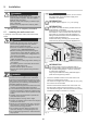
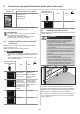
2. Connect one wire of the receiver to terminal (COM)
and the other wire to terminal (Signal).
3. Check the function after connecting the 2-wire safety
sensors.
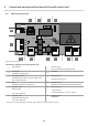
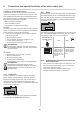
6.9 Functions of the buttons
1
2
3
4
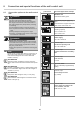
Fig. Wall control unit - buttons
• /HIW 7XUQWKHOLJKWLQJRQDQGRႇ
• (2) Middle = Open, stopp and close the door
• (3) Right = Locking or unlocking the opener
• (4) Upper right corner, status LED = red: Operator
locked, green: Operator unlocked
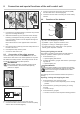
7XUQLQJWKHOLJKWLQJRQDQGRႇ
The button (1) lights up green when the wall station is
ready for operation and the opener is not locked.
1. Press the button (1).
Opener lighting switched on.
2. Pressing the button (1) again switches the opener light-
ing back off.
2SHQHUOLJKWLQJRႇ
INFORMATION
,IWKHRSHQHUOLJKWLQJLVQRWVZLWFKHGRႇPDQXDOO\
LWVZLWFKHVRႇDXWRPDWLFDOO\DIWHUPLQXWHV7KLV
value can be changed via SOMlink and a WiFi-
enabled device.
The lighting cannot be switched off when the opener is
moving.
Opening, closing and stopping the door
1. Press the button (2) to open and close.
The door opens or closes depending on the starting
position.
2. Press the button (2) during the opening or closing
process.
The door stops:
3. Press the button (2) again.
The door moves into the respective starting position.
4.
4.
1
1
4
6
5
1
2
3
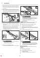
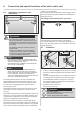
Fig. 3 Fig. 4 Fig. 5
3. Pre-attach the carriage bolt M6 (1) and the wing nut M6
(2) to the mounting bracket (3).
4. Slide the transmitter (4) over the head of the carriage
bolt M6 (1) and tighten the wing nut M6 (2). The posi-
tion of the safety sensors can be adjusted through the
slotted holes (5).
Mount the receiver on the opposite side in the same
way.
5. Run the two sets of wires (6) from the safety sensors to
the wall control unit.
6. Use staples to keep wires in place.
7. Connect to wall control unit.
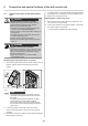
6.8 Connection of the safety sensors
The 2-wire safety sensors from SOMMER must be con-
nected to the wall control unit. Initial operation is not possi-
ble without the safety sensors. The safety sensors are au-
tomatically detected during initial operation.
INFORMATION
During initial operation, the safety sensors must
not be actuated or the sensors interrupted by
persons or objects.
Fig: Terminal block for the 2-wire safety sensors
TX RX
COM
Signal
Fig: Connecting diagramm for the 2-wire safety sensors
1. Connect one wire of the transmitter to terminal (COM)
and the other to terminal (Signal).