
Installation Guide


32
6. Connection and special functions of the wall control unit
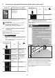
DIP switches on
the wall control
unit
ON OFF
5
S1
ON
12345
• No function • No function
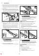
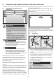
6.5 Installing the safety sensors
Please observe and comply with all instructions to ensure
a safe installation.
DANGER
Danger due to electric current!
Contact with live parts may result in electric
FXUUHQWÀRZLQJWKURXJKWKHERG\(OHFWULF
shock, burns or death may result.
` Installation, testing and replacement of elec-
trical components may only be carried out by
an electrician.
` The opener must be disconnected from the
power supply before working on the opener.
` If a battery pack is used, it must be discon-
nected.
` Then check that the opener is disconnected
from the power supply.
` Only connect the safety sensors to the
opener terminals in the wall control unit.
` Some local construction ordinances do not
allow an on-wall installation of wires. Please
check with your local building inspector.
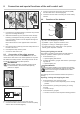
STOP
Fig. Test the safety sensors
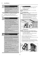
The safety sensors kit safeguards the door. If the safe-
ty sensors are breached, the door’s closing procedure is
stopped. If the door stops during closing because of the
safety sensors, it subsequently opens completely.
The opener only functions with the connected safety sen-
sors kit. Product contents see "3.5 Product contents for
safety sensor kit".
pcb section Function/application example
Terminal, 2-pin
wall button 2
potential-free
The version can vary depending on the type. This
means the use of accessories can vary.
INFORMATION
If a safety eye is used, it must not be actuated
when starting the programming.
If a safety eye is used as a frame safety eye,
move the door to the center position.
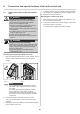
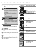
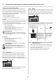
6.4 Setting the DIP switches on the wall
control unit
Special functions can be set up with the DIP switches
on the wall control unit.
All DIP switches are set to OFF by default.
NOTE
Do not use a metal object to set the DIP switches,
because this may damage the DIP switches or the
pcb.
Use a suitable tool to set the DIP switches, such
DVDÀDWSODVWLFREMHFW
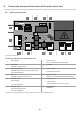
DIP switches on
the wall control
unit
ON OFF
1
S1
ON
12345
• %XWWRQGH¿QHG
door OPEN
• %XWWRQGH¿QHG
door CLOSE
• Button 1 pulse
sequence
• Button 2 lighting
function /partial
opening
2
S1
ON
12345
• "Relay" Door
status display:
Relay is activat-
ed during door
movement and
if the door is not
closed
• "Relay" lighting
function: Relay
can be used to
switch external
light
3
S1
ON
12345
• No function • No function
4
S1
ON
12345
• No function • No function