
Installation Guide


30
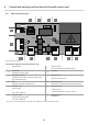
6. Connection and special functions of the wall control unit
6.2 Wall control unit pcb
Signal
COM
GND
+24V
~ 24 V AC
Light
gn
rt
+
-
SOMMER
Antriebs- u.
FunktechnikGmb
ACCU
GT-G-1
PCxxxxxxx
L`
N`
N
L
KEYPAD
1
4
S1
ON
12345
1
2
3 4
11
12
9
5
6
7
8
10
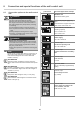
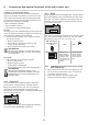
Fig. wall control unit pcb
Connection options to the wall control unit
1
DIP switches
7
Terminal, 2-pin
24 V AC transformer secondary side
2
ACCU slot
8
pcb label
Terminal for battery pack
3
Slot, keypad, black
9
Terminal, 2-pin
Terminal for the button connector cable of the
pro+ wall control unit
chain and rail, 24 V AC
4
Slot
10
Light slot, white
Terminal for RELAY, OUTPUT OC terminal for LUMI Strip supplementary lighting
5
Terminal, 2-pin
11
Terminal, 4-pin
power supply
• safety sensors
• external transformer, 24 V DC, 100 mA
120 V AC, 50/60 Hz
6
Terminal, 2-pin
12
Terminal, 2-pin
wall button
transformer primary side
120 V AC, 50/60 Hz
The version can vary depending on the type. This means the use of accessories can vary.