
Installation Guide


28
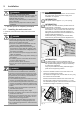
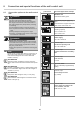
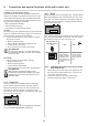
Feed the control cable into the wall control unit through
the cable inlet.
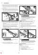
7. Shorten the control cable to no less than 7'' (174 mm)
in length, uncover the last 2'' (50 mm) and strip the
wires.
gn
rt
Fig. 8 Fig. 9
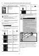
8. Remove the below strain relief.
Route the control cable in the wall control unit along
the transformer up to the gn/rt terminal.
Secure the control cable with the below strain relief to
prevent displacement.
9. Connect the
bu wire of the control cable to the gn
terminal.
Connect the brown wire of the control cable to the rt
terminal.
10. Close the housing in reverse order.
Installation of the wall control unit is complete.
Other connection options such as buttons
are described
in chapter "6. Connection and special funtions of the wall
control unit"
.
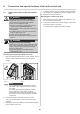
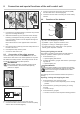
NOTE
The control unit cover is connected to the circuit
board of the wall control unit via a connection
cable.
If a battery pack has been installed, it is also
connected to the circuit board. Carefully remove
the control unit cover and unplug the connections.
This prevents damage to the wall control unit.
2. Loosen the screw on the wall unit of the control
unit cover and remove the control unit cover gently
upwards.
3. Unplug the connection cable for the membrane keypad
from the wall control unit.
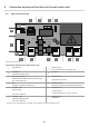
8,8
''
(224 mm)
2,95
''
(75 mm)
1,6
''
(40 mm)
1,6
''
(40 mm)
1/4
'' (
6 mm)
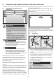
Fig. 4: Installation example
WARNING
Risk of eye injury!
&KLSVÀ\LQJZKHQGULOOLQJPD\FDXVHVHULRXV
injuries to eyes and hands.
` Wear safety glasses when drilling.
4. Transfer the mounting points to the substructure.
Drill two holes (Ø 1/4" x 1,6" / Ø 6 x 40 mm deep).
Insert the two wall plugs.
Affix the wall control unit with two screws and two
washers, align the unit and firmly tighten the screws.
Press the sealing plugs into the indentation to seal the
housing.
5. Route the control cable of the plug-in unit up to the wall
control unit and secure to prevent displacement.
2''
(50 mm)
7''
(174 mm)
Fig. 6 Fig. 7
6. Lay the control cable along the cable conduit on the
rear side of the wall control unit up to the cable inlet.
5. Installation