
Installation Guide


35
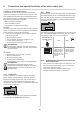
6. Connection and special functions of the wall control unit
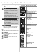
Locking or unlocking the opener
Unauthorized access can be prevented by locking the
opener. For example in the absence of the user or to pre-
vent unintentional activation with a handheld transmitter.
The following functions are deactivated in the factory set-
tings when the lock button is activated:
• Radio (handheld transmitter)
• Senso ventilation function
• Control device (corded external button)
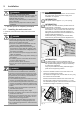
To lock:
The button (3) on the wall station lights up green when the
opener is unlocked. The button (3) lights up red when the
opener has been locked by the wall station.
1. Press and hold the button (3) for at least 5 seconds
with the door closed.
%XWWRQÀDVKHVJUHHQ
After 5 seconds, the button (3) lights up red.
Locking function activated.
All the functions of the opener are locked.
INFORMATION
If the door was still open, it can be closed using
the handheld transmitter. Only then are all opener
functions locked.
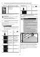
To unlock:
1. Press the button (3) for at least 5 seconds.
%XWWRQÀDVKHVUHG
Button (3) lights up green.
Locking function deactivated.
All the functions of the opener are activated again.
INFORMATION
All locking and unlocking functions can be
PRGL¿HGDQGDGMXVWHGZLWK620OLQNDQGD:L)L
enabled device. For more information ask your
specialist dealer.
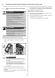
6.10 Output OC
The door status can be displayed with the Output OC
(open collector output) accessory. Optional, external
lighting (Lumi Strip) DC 24V max. 750 mA can also be
switched. The function depends on the setting of the
DIP switches. See also chapter "6.4 Setting the DIP switch-
es on the wall control unit".
PAD
1
4
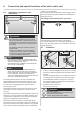
Fig. Relay slot for Output OC
The Output OC accessory part is plugged into the Relay
slot, see separate "Output OC" instructions.
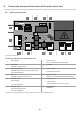
6.11 Relay
External lighting such as the garage light, courtyard light or
door status display can be controlled with the relay acces-
sory part. The function depends on the setting of the DIP
switches. See also chapter "6.4 Setting the DIP switches
on the wall control unit".
PAD
1
4
Fig. Relay slot
The Relay is plugged into the Relay slot on the wall control
unit, see separate "Relay" instructions. The max. switch-
ing capacity is 250 V AC, 5 A or 24 V DC, 5 A.
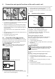
DIP switches on
the wall control
unit
ON OFF
2
S1
ON
12345
• "Relay" Door
status display:
Relay is activat-
ed during door
movement and
if the door is not
closed
• "Relay" lighting
function: Relay
can be used to
switch external
light
6.12 Installing the control unit cover of the
wall control unit
1. After working on the wall control unit, replace the con-
trol unit cover in reverse order, see "6.1 Control unit
cover of the wall control unit".
2. Connect the opener to the main power supply.
Check that the power supply is connected.