User's Manual
Table Of Contents
- Important Safety Instructions
- Overview
- The ERU assembly
- Do you have everything?
- Safety precautions
- Introduction
- Installing the ERU
- Installation overview
- Installation guidelines and requirements
- Estimating cable requirements
- Assembling the mounting bracket and pipe
- Installing the ERU on solid wood or lap siding
- Installing the ERU on brick or poured concrete
- Installing the ERU on a cinder-block or hollow wall
- Installing the ERU under the eaves
- Installing the ERU on a roof
- Attaching the ERU to the mounting assembly
- Routing and grounding the exterior cables
- Routing cable to the SOMAport
- Troubleshooting

53
Installing the ERU
Routing cable to the SOMAport
When routing cable to the SOMAport, you should select the shortest possible
path and always protect the cable from physical damage. Depending on the
installation site, you could run the cable through a floor or wall, or directly to the
SOMAport. If the cable goes straight through a wall, you can use a wall plate at
the access point.
The SOMAport
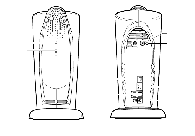
The following diagram shows the location of the ERU connector and ERU light
on the back panel of the SOMAport. When the light is green, the SOMAport is
using the ERU. When the light is not illuminated, the SOMAport is using its
internal antenna.
The lights on the front panel indicate the signal strength. The more lights that
are lit, the stronger the signal. However, even if no lights are lit, the SOMAport
may be able to function normally.
00316
Status Light
Signal Strength
Indicator Lights
Front Panel
USB Port
Telephone Jacks
ERU Connector
Ethernet Port
Back Panel
Power Jack
ERU Light


