
User's Manual Part 2

March 29, 2006 Part ######A revision 00a-DRAFT 69
Chapter 4: Base Station Installation Procedures
Shelf Layout
Utility Shelf Layout
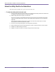
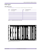
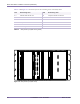
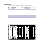
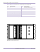
Table 4.1 and Figure 4.10 show the layout of the front-facing cards on the utility shelf.
Figure 4.10
Utility Shelf Layout (Front View)
Slot Front-Facing Card Slot Front-Facing Card
0–1 Power supply 0 12 Alarm card 0
2–3 Power supply 1 13 Alarm card 1
4–5 Power supply 2 14 Utility bus controller 1
6 Ethernet switch 0 15–16 Hard disk drive 1
7–8 Hard disk drive 0 17 —
9— 18—
10 Utility bus controller 0 19 Ethernet switch 1
11 — 20 —
Table 4.1
Utility Shelf Layout (Front-Facing Cards)
0-1 2-3 4-5 6 7-8 9 10 11 12 13 14 15-16
17
19 20
- 12V
+ 12V
+ 3.3 V
+ 5V
FAULT
PWR
- 12V
+ 12V
+ 3.3 V
+ 5V
FAULT
PWR
HDD
Activity
SCSI
Activity
HDD
Activity
SCSI
Activity
- 12V
+ 12V
+ 3.3 V
+ 5V
FAULT
PWR
- 12V
+ 12V
+ 3.3 V
+ 5V
FAULT
PWR
18
- 12V
+ 12V
+ 3.3 V
+ 5V
FAULT
PWR
- 12V
+ 12V
+ 3.3 V
+ 5V
FAULT
PWR
HDD
Activity
SCSI
Activity
HDD
Activity
SCSI
Activity