
User's Manual Part 2


March 29, 2006 Part ######A revision 00a-DRAFT 107
Chapter 6: On-Site Configuration procedures
Configure the Ethernet Switches
In order to operate in the base station, the Ethernet switches require custom settings. You need to
configure the Ethernet switches only once; the configuration is stored in the switch’s nonvolatile
memory.
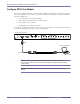
You can connect to the Ethernet switch by connecting a custom serial cable with a null modem
adapter to the console port located on the front panel.
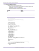
Figure 6.2 shows the connections for the Ethernet switch serial cable.
Figure 6.2
Ethernet Switch Serial Cable
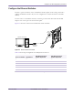
Table 6.4 shows the pin assignments for the RJ-45 serial connector.
RJ-45
Connector
00331
Diagnostic Access Port
DB9 Female
Connector
RJ-11 Pin Number Signal Name
DCE DB-9 Connector
Number Equivalent
DCE DB-9 Connector
Number Equivalent
1—— —
2GND5 5
3RX3 2
4TX2 3
5GND
6—— —
Table 6.4
Ethernet Switch RJ-45 Serial Connector Pin Assignments