
User's Manual Part 2


March 29, 2006 Part ######A revision 00a-DRAFT 105
Chapter 6: On-Site Configuration procedures
To configure the GPS clock module
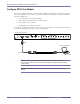
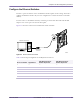
1 Connect a laptop to the GPS clock, as shown in Figure 6.1.
NOTE: The control cable is the cable that connects the GPS clock module to the
GPS CNTL port on the alarm card.
2 Start a serial terminal session using the settings shown in Table 6.3.
NOTE: Depending on your communications software, you may need to append a
linefeed to each issued command (in addition to the pressing Enter). In Minicom on
Linux, use Control+J. For example:
$SSTA* <ENTER> <CTRL-J>
.
3 Set the compensation for the antenna cable delay:
i Calculate the cable delay by multiplying the total cable length by the delay value. For example, if the
delay value of the cable is 4.36 ns/m and there is 15 m of cable, then the cable delay would be 15 m
x 4.36 ns/m = 65.4 ns. Round the result to the nearest nanosecond. In this case, the result would be
65 ns.
ii Set the cable delay for the first GPS plug-in module. This example uses a cable delay of 65 ns.
Replace the 65 in the following command with your own calculated cable delay value:
$ANT1,65*
↵
iii Set the cable delay for the second GPS plug-in module. Again, replace the 65 in the following
command with your own calculated cable delay value:
$ANT2,65*
↵
The GPS clock module briefly enters coasting mode as it recalculates its position.
4 Set the automatic determination of antenna position for each module:
$PMD1,S*
↵
$PMD2,S*
↵
The GPS clock module enters Survey module and recalculates its position.
5 Configure the GPS output to be expressed in UTC time:
$TIMM,1*
↵
$TIMM,2*
↵
The GPS clock module is now configured.
Parameter Setting
Baud 9600 bits/s
Data bits 8
Parity None
Stop bits 1
Flow control None
ASCII setup Send linefeeds, local character echo on
Table 6.3
GPS Clock Module Serial Port Settings