
User's Manual Part 2

102 Part ######A revision 00a-DRAFT March 29, 2006
Macro Base Station Installation Procedures (NPM-1000)
Power On the Base Station
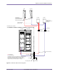
The power for the base station is controlled by circuit breakers in the PDP, located at the top of each
rack. Each power supply, RFSS module, cooling unit, and GPS clock module has its own circuit
breaker, which means it can be powered on and off independently of the other devices.
To power on the base station
1 Ensure that your main DC power supply is powered on and is providing a power source that meets the
electrical requirements listed on 23.
2 Power on the upper and lower cooling units. On each rack, set breakers CB 01 and CB 14 to the ON (up)
position.
The fans will start turning. If the fans do not start, ensure that the SGNL port on each cooling unit is
connected to the alarm wiring card. The fans will turn only when the alarm cable is present.
3 Power on each power supply in the utility and radio shelves separately.
NOTE: The red OUTPUT FAIL light on each power supply turns off within 3 s. If the
OUTPUT FAIL light remains on or flickers continuously, power down the shelf
immediately and replace the power supply.
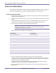
Table 6.1 shows the circuit breakers for each power supply.
4 Power on the GPS clock module, if present, by setting CB 15 to the ON (up) position.
The GPS clock module will perform its internal diagnostics and begin to acquire and track satellites. It
may take up to 30 min for the GPS receivers to acquire a rough position and time. The accuracy of the
receivers improves as the satellites are tracked.
See AccuSync-R GPS Synchronized Time and Frequency Instrument User’s Manual (377-8006),
available from Zyfer Inc., for information about the GPS clock module.
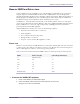
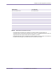
5 Power on each RFSS module in the RF rack separately. Table 6.2 shows the circuit breakers for the
RFSS modules.
Power Supply Circuit Breaker
Radio shelf 0, PS0 (slots 0–1) Radio rack PDP, CB 02
Radio shelf 0, PS1 (slots 2–3) Radio rack PDP, CB 03
Radio shelf 0, PS2 (slots 4–5) Radio rack PDP, CB 04
Radio shelf 1, PS0 (slots 0–1) Radio rack PDP, CB 05
Radio shelf 1, PS1 (slots 2–3) Radio rack PDP, CB 06
Radio shelf 1, PS2 (slots 4–5) Radio rack PDP, CB 07
Radio shelf 2, PS0 (slots 0–1) Radio rack PDP, CB 08
Radio shelf 2, PS1 (slots 2–3) Radio rack PDP, CB 09
Radio shelf 2, PS2 (slots 4–5) Radio rack PDP, CB 10
Utility shelf, PS0 (slots 0–1) Radio rack PDP, CB 11
Utility shelf, PS1 (slots 2–3) Radio rack PDP, CB 12
Utility shelf, PS2 (slots 4–5) Radio rack PDP, CB 13
Table 6.1
Utility and Radio Shelf Power Supply Circuit Breaker Summary