
User's Manual Part 2


98 Part ######A revision 00a-DRAFT March 29, 2006
Macro Base Station Installation Procedures (NPM-1000)
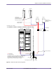
3 Carefully disconnect the RF equipment and cables you want to test.
4 Connect the cable sweep analyzer to the equipment and cables you want to test.
NOTE: Be careful not to damage any cables or connectors when connecting the
analyzer to the RF equipment.
Due to the use of the tower-mounted amplifier (TMA), all cable sweeps must measure
the total length of the cable run (including all connectors, jumpers, and CIN), using a
DIN adapter (female-female) in place of the TMA.
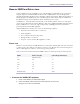
5 Perform the cable sweeps for your base station’s supported spectrum, as listed in Table 5.2.
See the documentation that comes with your analyzer for information about performing the cable sweep
and interpreting the results.
6 Record the results from the cable sweeps according to the methods and procedures of your site.
Keeping records of periodic cable sweeps makes troubleshooting future problems easier.
7 Carefully disconnect the analyzer from the RF equipment.
8 Reconnect the RF equipment and cables back to the RFSS module.
9 If any of the connectors are outdoors, ensure that they are resealed according to the procedures of your
site.
10 Reconnect the RF equipment to the RFSS module.
11 Power on the RFSS module. See page 108 for a list of circuit breakers.
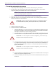
!
WARNING: Extreme care must be taken when connecting or disconnecting the
coaxial antenna cable to avoid damage to the center pins. Connectors should be
torqued to a maximum of 17 foot-pounds and be free of dirt or moisture. Do not
over-torque the connectors as this can damage the center pin and cause cable faults
and other RF problems.
Model Spectrum
PCS 1850–1990 MHz
MMDS 2500–2686 MHz
WCS 2305–2355 MHz
Table 5.2
Supported Base Station Spectrum