
User's Manual Part 2

90 Part ######A revision 00a-DRAFT March 29, 2006
Macro Base Station Installation Procedures (NPM-1000)
Connect Ferrite Blocks
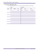
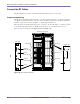
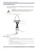
Ferrite blocks are required on some alarm and IF/RF signal cables for regulatory compliance. Figure
4.19 shows which cables on the alarm wiring and IF/RF cards require ferrite blocks.
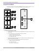
Figure 4.19
Ferrite Block Installation
To connect ferrite blocks to cables
1 Connect a ferrite block to each IF/RF card’s pair of SGNL MAIN and DIV cables. One ferrite block is used
for both cables.
2 Connect a ferrite block to each of the following alarm wiring card cables:
UPPER and LOWER COOLING RF cables
UPPER and LOWER COOLING RADIO cables
RF and RADIO PDP cables
3 Connect two ferrite blocks to the alarm wiring card’s UPPER COOLING RF and RADIO cables. Each
ferrite block is connected to both cables.
4 Connect one ferrite block to the following pairs of cables on the alarm wiring card:
LOWER COOLING RF and RADIO cables
RF and RADIO PDP cables
GPS CONTROL and ALARM cables
RF
UPPER
COOLING
RADIO
UPPER
COOLING
GPS
CONTROL
GPS
ALARM
RF
LOWER
COOLING
RADIO
LOWER
COOLING
RF
PDP
RADIO
PDP
AUX SITE
Alarm Wiring Card
Ferrite Block
S
G
NL
D
IV
SG
NL
M
AIN
IF/RF Card
Ferrite Block
R
X
M
AIN
TX
M
AIN
R
X
DIV
R
X
D
I
V