
User's Manual Part 2

March 29, 2006 Part ######A revision 00a-DRAFT 87
Chapter 4: Base Station Installation Procedures
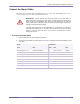
Connect the Clock Cables
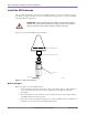
The GPS clock module receives its timing signals from the GPS antennas via two coaxial cables with
male TNC connectors on each end. The clock cables use 0.195-inch coaxial cables with male SMA
connectors to distribute the timing signals to the clock wiring cards.
NOTE: Clock cables are only required on +24V base stations. Base stations
configured for –48V operation use a clock source card and do not require clock cables
or a GPS clock module.
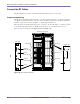
Component Numbering
The radio shelves are numbered from bottom to top (that is, the bottom shelf is “0” and the top shelf
is “2”). Each radio shelf contains two rear-facing clock wiring cards, one in slot 11 and one in slot 16.
The GPS clock module outputs are numbered from left to right when viewed from the back of the
base station.
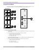
To connect the clock cables
1 Connect the two GPS antenna cables to the Antenna 1 and Antenna 2 ports located on the rear of the
GPS clock module.
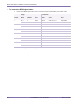
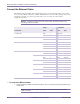
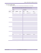
2 Connect the GPS clock module to the clock wiring cards using the clock cables. Table 4.11 shows the
origin and termination point of each cable.
NOTE: The minimum bend radius for clock cables is 2.54 cm (1.0 inch).
Sector
Origin Termination
Module Port Shelf Card Port
1 GPS FREQUENCY OUT 1 Radio 0 clock wiring (slot 11) FREQUENCY
2 GPS FREQUENCY OUT 2 Radio 0 clock wiring (slot 16) FREQUENCY
3 GPS FREQUENCY OUT 3 Radio 1 clock wiring (slot 11) FREQUENCY
4 GPS FREQUENCY OUT 4 Radio 1 clock wiring (slot 16) FREQUENCY
5 GPS FREQUENCY OUT 5 Radio 2 clock wiring (slot 11) FREQUENCY
6 GPS FREQUENCY OUT 6 Radio 2 clock wiring (slot 16) FREQUENCY
Table 4.11
Clock Cable Summary