
User's Manual Part 2

86 Part ######A revision 00a-DRAFT March 29, 2006
Macro Base Station Installation Procedures (NPM-1000)
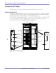
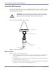
Connect the Ethernet Cables
The Ethernet cables are CAT5 cables with RJ-45 connectors on each end. The cables connect radio
sector controllers (RSC), utility bus controllers (UBC), Ethernet switches (SW), and edge routers. The
two Ethernet switches are connected together with a cross-over cable; the other cards use
straight-through cables.
NOTE: The Ethernet cabling is done via rear I/O cards. The Ethernet ports on the
front-facing cards are not used.
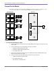
To connect the Ethernet cables
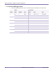
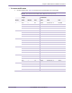
1 Connect the Ethernet cables to the Ethernet switches. Table 4.10 shows the origin and termination point
of each cable.
NOTE: See your field engineering package for information about your edge router
cable connections.
Connection
Origin Termination
Card Port Card Port
To edge router SW0 1 Edge router
SW1 1 Edge router
Cross-over to other Ethernet switch SW0 3 SW1 3
SW0 4 SW1 4
Utility bus controllers SW0 5 UBC0 eth0 (A)
SW0 6 UBC1 eth0 (A)
SW1 5 UBC0 eth1 (B)
SW1 6 UBC1 eth1 (B)
Radio sector controllers Sector 1 SW0 7 RSC0 eth0 (A)
SW1 7 RSC0 eth1 (B)
Sector 2 SW0 8 RSC1 eth0 (A)
SW1 8 RSC1 eth1 (B)
Sector 3 SW0 9 RSC2 eth0 (A)
SW1 9 RSC2 eth1 (B)
Sector 4 SW0 10 RSC3 eth0 (A)
SW1 10 RSC3 eth1 (B)
Sector 5 SW0 11 RSC4 eth0 (A)
SW1 11 RSC4 eth1 (B)
Sector 6 SW0 12 RSC5 eth0 (A)
SW1 12 RSC5 eth1 (B)
Table 4.10
Ethernet Cabling