
User's Manual Part 2

84 Part ######A revision 00a-DRAFT March 29, 2006
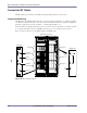
Macro Base Station Installation Procedures (NPM-1000)
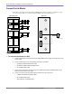
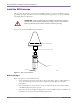
To connect the RFSS signal cables
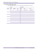
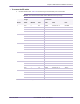
1 Connect each RFSS signal cable. Table 4.8 shows the origin and termination point of each cable.
Sector
Origin Termination
Shelf Module Port Shelf Card Port
1 RF 0 0 SGNL Radio 0 IF/RF slot 10–11 SGNL MAIN
RF 0 1 SGNL Radio 0 IF/RF slot 10–11 SGNL DIV
2 RF 0 2 SGNL Radio 0 IF/RF slot 15–16 SGNL MAIN
RF 0 3 SGNL Radio 0 IF/RF slot 15–16 SGNL DIV
3 RF 1 0 SGNL Radio 1 IF/RF slot 10–11 SGNL MAIN
RF 1 1 SGNL Radio 1 IF/RF slot 10–11 SGNL DIV
4 RF 1 2 SGNL Radio 1 IF/RF slot 15–16 SGNL MAIN
RF 1 3 SGNL Radio 1 IF/RF slot 15–16 SGNL DIV
5 RF 2 0 SGNL Radio 2 IF/RF slot 10–11 SGNL MAIN
RF 2 1 SGNL Radio 2 IF/RF slot 10–11 SGNL DIV
6 RF 2 2 SGNL Radio 2 IF/RF slot 15–16 SGNL MAIN
RF 2 3 SGNL Radio 2 IF/RF slot 15–16 SGNL DIV
Table 4.8
RFSS Signal Cable Summary