
User's Manual Part 2

March 29, 2006 Part ######A revision 00a-DRAFT 81
Chapter 4: Base Station Installation Procedures
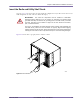
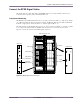
NOTE: Base stations supporting less than six sectors will have empty radio shelves
that do not require power.
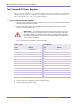
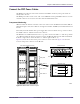
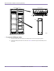
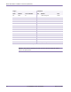
3 Connect each PDP power cable in the RF rack. The power connectors for the RFSS module are located
at the back of the rack. Table 4.7 shows the origin and termination point of each cable.
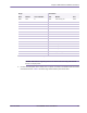
Origin Termination
Rack Module Circuit Breaker Rack Module Port
Radio PDP 01 Radio Lower cooling unit Power
Radio PDP 02 Radio Radio shelf 0 PS0
Radio PDP 03 Radio Radio shelf 0 PS1
Radio PDP 04 Radio Radio shelf 0 PS2
Radio PDP 05 Radio Radio shelf 1 PS0
Radio PDP 06 Radio Radio shelf 1 PS1
Radio PDP 07 Radio Radio shelf 1 PS2
Radio PDP 08 Radio Radio shelf 2 PS0
Radio PDP 09 Radio Radio shelf 2 PS1
Radio PDP 10 Radio Radio shelf 2 PS2
Radio PDP 11 Radio Utility shelf PS0
Radio PDP 12 Radio Utility shelf PS1
Radio PDP 13 Radio Utility shelf PS2
Radio PDP 14 Radio Upper cooling unit Power
Radio PDP 15 Radio GPS clock module Power
Table 4.6
Radio Rack Power Cable Summary