
User's Manual Part 2

March 29, 2006 Part ######A revision 00a-DRAFT 79
Chapter 4: Base Station Installation Procedures
Connect the PDP Power Cables
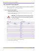
The PDP power cables for each rack are attached to the PDP at the factory. The power cables are
already tied to the rack.
The PDP power cables consist of #10, #12, or #16 AWG wire with 3-pin DSUB connectors on each
end. The connectors are secured to the racks with 1/8-inch flathead screws.
Component Numbering
When viewed from the back of the base station, the connectors for the PDP circuit breakers (CB) are
labeled from right to left (that is, CB 01 is the right-most breaker and CB 15 is the third breaker from
the left).
Each utility and radio shelf has three power supply (PS) connectors: PS2 is the top connector, PS0 is
the middle connector, and PS1 is the bottom connector.
The RF shelves are numbered from bottom to top (that is, the bottom shelf is “0” and the top shelf is
“2”). When viewed from the front of the base station, the RFSS modules in each shelf are numbered
from left to right (that is, the left module is “0” and the right module is “3”).
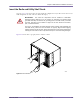
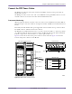
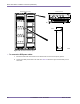
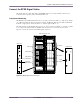
Figure 4.15 shows the location of the power connectors on the radio rack. Figure 4.16 shows the
location of the power connectors on the RF rack.
Figure 4.15
Radio Rack Connector Layout
00454
Radio Shelf #0
CB 01
Radio Rack PDP
Radio Shelf #1
Radio Shelf #2
Utility Shelf
PS2
PS0
PS1
Base Station Racks (Rear View)
Utility/Radio Shelf
CB 15