
User's Manual Part 2

74 Part ######A revision 00a-DRAFT March 29, 2006
Macro Base Station Installation Procedures (NPM-1000)
Test CompactPCI Power Supplies
This procedure describes how to test the CompactPCI power supplies and shelves for electrical faults.
Testing the power supplies and shelves before inserting the cards ensures that, in the unlikely event
that an electrical fault does occur, no cards will be damaged.
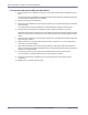
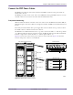
To test CompactPCI power supplies
1 Ensure that your main DC power supply is powered on and is providing a power source that meets the
electrical requirements listed on page 23.
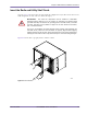
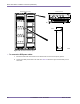
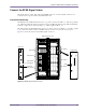
2 Power on each power supply in the utility and radio shelves separately. Wait at least 10 s before
powering on the next power supply.
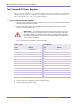
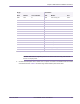
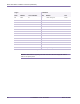
Table 4.5 shows the circuit breakers for each power supply.
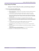
3 Power off all the power supplies in the radio and utility shelves.
4 Power off your main DC power supply.
WARNING: The red OUTPUT FAIL light on each power supply should turn off
within 3 s. If the OUTPUT FAIL light remains on or flickers continuously, power down
the shelf immediately and replace the power supply. If the replacement power supply
also indicates a fault condition, your shelf may be damaged. Replace the shelf before
continuing with the installation.
Power Supply Circuit Breaker
Shelf Module Rack Number
Radio 0 Left (slots 0–1) Radio 02
Radio 0 Middle (slots 2–3) Radio 03
Radio 0 Right (slots 4–5) Radio 04
Radio 1 Left (slots 0–1) Radio 05
Radio 1 Middle (slots 2–3) Radio 06
Radio 1 Right (slots 4–5) Radio 07
Radio 2 Left (slots 0–1) Radio 08
Radio 2 Middle (slots 2–3) Radio 09
Radio 2 Right (slots 4–5) Radio 10
Utility Left (slots 0–1) Radio 11
Utility Middle (slots 2–3) Radio 12
Utility Right (slots 4–5) Radio 13
Table 4.5
Utility and Radio Shelf Power Supply Circuit Breaker Summary