Macro Base Station Installation Procedures (NPM-1000) Attach the Utility Shelf to the Radio Rack The utility shelf is installed in the top-most bay in the radio rack. To attach the utility shelf to the radio rack 1 Remove the utility shelf from its protective bag. You can distinguish the utility shelf from the radio shelves by reading the manufacturer’s label on the inside of the shelf. 2 Slide the utility shelf into the top bay in the radio rack.
Chapter 4: Base Station Installation Procedures Install the GPS Clock Module The Global Positioning System (GPS) clock module consists of a 1U module that contains two plug-in GPS receivers. The GPS clock module requires two GPS antennas. GPS antenna installation is described on page 92. N O T E : The GPS clock module is only used in +24V base stations. Base stations configured for –48V power use clock source cards instead. See “Insert the Radio and Utility Shelf Cards” on page 75 for information.
Macro Base Station Installation Procedures (NPM-1000) Install the RFSS Modules If the configuration of your base station does not require a full complement of RFSS modules, some slots may be covered with filler panels. C A U T I O N : Each RFSS module weighs approximately 15 kg (33 pounds). ! To insert the RFSS modules in the RF rack 1 Remove the RFSS module from its protective bag. 2 Orient the RFSS module so that the text on the front panel is right-side up.
Chapter 4: Base Station Installation Procedures Cover Empty RFSS Slots Any empty slots in the RF shelves should be covered with RFSS filler panels. The RFSS filler panels protect the other RFSS modules from dust and ensure the required air flow to the installed RFSS modules. To cover unused slots with RFSS filler panels 1 Remove the RFSS filler panel from its protective bag. 2 Orient the filler panel so that the text on the front panel is right-side up.
Macro Base Station Installation Procedures (NPM-1000) POPULATING THE SHELVES These procedures describe how to install the CompactPCI power supplies and cards into the utility and radio shelves. Procedure Page Insert CompactPCI Power Supplies 73 Test CompactPCI Power Supplies 74 Insert the Radio and Utility Shelf Cards 75 Cover Unused Card Slots 77 N O T E : Your base station may arrive with the shelves already populated.
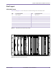
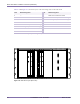
Chapter 4: Base Station Installation Procedures Shelf Layout Utility Shelf Layout Table 4.1 and Figure 4.10 show the layout of the front-facing cards on the utility shelf.
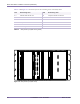
Macro Base Station Installation Procedures (NPM-1000) Table 4.2 and Figure 4.11 show the layout of the rear-facing cards on the utility shelf. Slot Rear-Facing Card Slot Rear-Facing Card 6–7 Ethernet switch rear I/O card 14 Utility bus controller rear I/O card 8 — 15 — 9 — 16 — 10 Utility bus controller rear I/O card 17 — 11 — 18 — 12–13 Alarm wiring card 19–20 Ethernet switch rear I/O card Table 4.
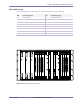
Chapter 4: Base Station Installation Procedures Radio Shelf Layout Table 4.3 and Figure 4.12 show the layout of the front-facing cards on the radio shelf.
Macro Base Station Installation Procedures (NPM-1000) Table 4.4 and Figure 4.13 show the layout of the rear-facing cards on the radio shelf.
Chapter 4: Base Station Installation Procedures Insert CompactPCI Power Supplies The radio and utility shelves each contain two or three identical CompactPCI power supplies. See pages 69 and 71 for the locations of the power supplies. Utility shelves and completely filled radio shelves use three power supplies each; half-full radio shelves require only two power supplies. This ensures that the shelves will continue to operate should one of the power supplies fail.
Macro Base Station Installation Procedures (NPM-1000) Test CompactPCI Power Supplies This procedure describes how to test the CompactPCI power supplies and shelves for electrical faults. Testing the power supplies and shelves before inserting the cards ensures that, in the unlikely event that an electrical fault does occur, no cards will be damaged.
Chapter 4: Base Station Installation Procedures Insert the Radio and Utility Shelf Cards See pages 69 to 72 for the location of each card. If the configuration of your base station does not use a full complement of cards, some slots will be left empty. WARNING: The cards use components that are sensitive to electrostatic discharges (ESD). Make sure you are wearing an approved and regularly tested grounded wrist strap connected to the grounding point on the PDP.
Macro Base Station Installation Procedures (NPM-1000) To insert the cards into the utility and radio shelves 1 Ensure that there are no obstructions in the slot or on the guide rails and check the backplane for bent pins. If there are bent pins, the backplane is damaged and requires repair. Report any damaged equipment to your field support coordinator as soon as possible. 2 Remove the card from its antistatic bag.
Chapter 4: Base Station Installation Procedures Cover Unused Card Slots Any empty slots in the radio and utility shelves should be covered with filler panels. The filler panels ensure airflow to the other cards and protect the cards from dust and electromagnetic interference. To cover the unused slots with filler panels 1 Remove the filler panel from its protective bag.
Macro Base Station Installation Procedures (NPM-1000) CONNECTING THE CABLES This section describes the cables connecting the different systems in the base station. Procedure Page Connect the PDP Power Cables 79 Connect the RFSS Signal Cables 83 Connect the Alarm Cables 85 Connect the Ethernet Cables 86 Connect the Clock Cables 87 Connect the RF Cables 88 Connect Ferrite Blocks 90 N O T E : The cables are packaged according to their type.
Chapter 4: Base Station Installation Procedures Connect the PDP Power Cables The PDP power cables for each rack are attached to the PDP at the factory. The power cables are already tied to the rack. The PDP power cables consist of #10, #12, or #16 AWG wire with 3-pin DSUB connectors on each end. The connectors are secured to the racks with 1/8-inch flathead screws.
Macro Base Station Installation Procedures (NPM-1000) NPM Racks (Rear View) Radio Rack PDP CB 15 CB 01 Power 00448 Figure 4.16 RF Rack Connector Layout To connect the PDP power cables 80 1 Ensure that each PDP circuit breaker in the radio and RF rack is in the OFF (down) position. 2 Connect each PDP power cable in the radio rack. Table 4.6 shows the origin and termination point of each cable.
Chapter 4: Base Station Installation Procedures Origin Termination Rack Module Circuit Breaker Rack Module Port Radio PDP 01 Radio Lower cooling unit Power Radio PDP 02 Radio Radio shelf 0 PS0 Radio PDP 03 Radio Radio shelf 0 PS1 Radio PDP 04 Radio Radio shelf 0 PS2 Radio PDP 05 Radio Radio shelf 1 PS0 Radio PDP 06 Radio Radio shelf 1 PS1 Radio PDP 07 Radio Radio shelf 1 PS2 Radio PDP 08 Radio Radio shelf 2 PS0 Radio PDP 09 Radio Radio shelf 2 PS
Macro Base Station Installation Procedures (NPM-1000) Origin Termination Rack Module Circuit Breaker Rack Module Port RF PDP 01 RF Lower cooling unit Power RF PDP 02 RF RF shelf 0, RFSS module 0 PWR RF PDP 03 RF RF shelf 0, RFSS module 1 PWR RF PDP 04 RF RF shelf 0, RFSS module 2 PWR RF PDP 05 RF RF shelf 0, RFSS module 3 PWR RF PDP 06 RF RF shelf 1, RFSS module 0 PWR RF PDP 07 RF RF shelf 1, RFSS module 1 PWR RF PDP 08 RF RF shelf 1, RFSS module 2 PWR
Chapter 4: Base Station Installation Procedures Connect the RFSS Signal Cables The signal cables are serial cables with 9-pin DSUB connectors on each end. The connectors are secured to their receptacles with 1/8-inch flathead screws. Component Numbering The RF shelves are numbered from bottom to top (that is, the bottom shelf is “0” and the top shelf is “2”).
Macro Base Station Installation Procedures (NPM-1000) To connect the RFSS signal cables 1 Connect each RFSS signal cable. Table 4.8 shows the origin and termination point of each cable.
Chapter 4: Base Station Installation Procedures Connect the Alarm Cables The alarm cables are serial cables with DSUB connectors on each end. The DSUB connectors are secured to their receptacles with 1/8-inch flathead screws. W A R N I N G : Ensure that the main DC power supply for the base station is powered off before connecting the alarm cables. The PDP alarm cables are hot at all times and are not hot-swappable, even when the circuit breakers in the PDP are powered OFF (down).
Macro Base Station Installation Procedures (NPM-1000) Connect the Ethernet Cables The Ethernet cables are CAT5 cables with RJ-45 connectors on each end. The cables connect radio sector controllers (RSC), utility bus controllers (UBC), Ethernet switches (SW), and edge routers. The two Ethernet switches are connected together with a cross-over cable; the other cards use straight-through cables. N O T E : The Ethernet cabling is done via rear I/O cards.
Chapter 4: Base Station Installation Procedures Connect the Clock Cables The GPS clock module receives its timing signals from the GPS antennas via two coaxial cables with male TNC connectors on each end. The clock cables use 0.195-inch coaxial cables with male SMA connectors to distribute the timing signals to the clock wiring cards. N O T E : Clock cables are only required on +24V base stations.
Macro Base Station Installation Procedures (NPM-1000) Connect the RF Cables The RF cables are 0.195-inch coaxial cables with male SMA connectors on each end. Component Numbering The RF shelves are numbered from bottom to top (that is, the bottom shelf is “0” and the top shelf is “2”). When viewed from the front of the base station, the RFSS modules in each shelf are numbered from left to right (that is, the left module is “0” and the right module is “3”).
Chapter 4: Base Station Installation Procedures To connect the RF cables 1 Connect each RF cable. Table 4.12 shows the origin and termination point of each cable. N O T E : The minimum bend radius for RF cables is 2.54 cm (1.0 inch).
Macro Base Station Installation Procedures (NPM-1000) Connect Ferrite Blocks Ferrite blocks are required on some alarm and IF/RF signal cables for regulatory compliance. Figure 4.19 shows which cables on the alarm wiring and IF/RF cards require ferrite blocks.
Chapter 5 ANTENNA INSTALLATION PROCEDURES Chapter 5 This chapter provides an overview of the installation process. Please familiarize yourself with the installation process in general before proceeding to the next chapter. Contents Install the GPS Antennas .............................................................................................................................. Install the Main and Diversity Antennas .....................................................................................
Macro Base Station Installation Procedures (NPM-1000) Install the GPS Antennas This procedure describes how to install two Zyfer GPS antennas on top of 1-inch-diameter, hollow pipes using the supplied hardware. Consult your field engineering package for any site-specific GPS antenna installation requirements.
Chapter 5: Antenna Installation Procedures To install the GPS antennas 1 Run the two coaxial cables supplied with each antenna from the racks to the intended location of the GPS antennas, such as the base station’s roof or tower. N O T E : Ensure that the cable remains clear of any sources of potential interference, such as transmitting equipment or power lines. 2 Vertically install two 1-inch-diameter pipes in a location that provides the maximum unobstructed view of the sky.
Macro Base Station Installation Procedures (NPM-1000) Install the Main and Diversity Antennas This procedure describes the general process for installing the main and diversity antennas. Consult your field engineering package for any site-specific antenna installation requirements.
Chapter 5: Antenna Installation Procedures Main Diversity Antennas use 7/16 DIN(M) connectors (MMDS antennas may use N-type connectors) TT-LNA TT-LNA TT-LNAs use 7/16(M) connectors for all ports 1/2-inch superflex Jumper (4 feet) Antenna BTS Antenna BTS Demarcation point of shelter RF Rack 7/16 DIN(M) Radio Rack 7/16 DIN(F) Feeds (hard line) Red is Main Run Blue is Diversity Run 7/16 DIN(F) On additional runs (that is, the cabling for additional sectors), label antenna cables with additio
Macro Base Station Installation Procedures (NPM-1000) To install the main and diversity antennas 1 Verify that you have the right type of antennas, both in terms of frequency and direction. 2 Run the antenna cable from the racks to the intended location of each antenna. See your field engineering package and installation MOP for antenna cable specifics. N O T E : Ensure that the cable remains clear of any sources of potential interference, such as transmitting equipment or power lines.
Chapter 5: Antenna Installation Procedures Measure VSWR and Return Loss Voltage standing wave ratio (VSWR) is a ratio of the maximum to minimum voltage as measured along the length of a mismatched RF transmission line. VSWR indicates the level of impedance matching between RF equipment (such as amplifiers, cabling, and antennas). When the impedances of the RF equipment are mismatched, some of the RF energy is reflected back along the transmission line.
Macro Base Station Installation Procedures (NPM-1000) 3 Carefully disconnect the RF equipment and cables you want to test. W A R N I N G : Extreme care must be taken when connecting or disconnecting the ! 4 coaxial antenna cable to avoid damage to the center pins. Connectors should be torqued to a maximum of 17 foot-pounds and be free of dirt or moisture. Do not over-torque the connectors as this can damage the center pin and cause cable faults and other RF problems.
Chapter 5: Antenna Installation Procedures Measure the Distance to a Fault Distance-to-fault (DTF) is a measurement of VSWR or return loss based on distance. A DTF test indicates the distance to a short, open, or load. Perform a DTF test whenever a VSWR test reveals that the antenna system is not operating within specifications. To accurately interpret the results from a DTF cable sweep, you need to know the lengths of your cables and the location of any devices or connectors attached to those cables.
Macro Base Station Installation Procedures (NPM-1000) 100 Part ######A revision 00a-DRAFT March 29, 2006
Chapter 6 ON-SITE CONFIGURATION PROCEDURES Chapter 6 This chapter describes how to power on the base station and configure the cards. Contents Configure GPS Clock Module ..................................................................................................................... 104 Configure the Ethernet Switches ................................................................................................................ 107 Post-Installation Activities .......................................
Macro Base Station Installation Procedures (NPM-1000) Power On the Base Station The power for the base station is controlled by circuit breakers in the PDP, located at the top of each rack. Each power supply, RFSS module, cooling unit, and GPS clock module has its own circuit breaker, which means it can be powered on and off independently of the other devices.
Chapter 6: On-Site Configuration procedures RFSS Module Circuit Breaker RF shelf 0, RFSS module 0 RF rack PDP, CB 02 RF shelf 0, RFSS module 1 RF rack PDP, CB 03 RF shelf 0, RFSS module 2 RF rack PDP, CB 04 RF shelf 0, RFSS module 3 RF rack PDP, CB 05 RF shelf 1, RFSS module 0 RF rack PDP, CB 06 RF shelf 1, RFSS module 1 RF rack PDP, CB 07 RF shelf 1, RFSS module 2 RF rack PDP, CB 08 RF shelf 1, RFSS module 3 RF rack PDP, CB 09 RF shelf 2, RFSS module 0 RF rack PDP, CB 10 RF shelf 2, RF
Macro Base Station Installation Procedures (NPM-1000) Configure GPS Clock Module Base stations configured for +24V operation require a GPS clock module for synchronization purposes over the air interface.
Chapter 6: On-Site Configuration procedures To configure the GPS clock module 1 Connect a laptop to the GPS clock, as shown in Figure 6.1. N O T E : The control cable is the cable that connects the GPS clock module to the GPS CNTL port on the alarm card. 2 Start a serial terminal session using the settings shown in Table 6.3. Parameter Setting Baud 9600 bits/s Data bits 8 Parity None Stop bits 1 Flow control None ASCII setup Send linefeeds, local character echo on Table 6.
Macro Base Station Installation Procedures (NPM-1000) N O T E : It may take several hours for the GPS clock module to determine its position.
Chapter 6: On-Site Configuration procedures Configure the Ethernet Switches In order to operate in the base station, the Ethernet switches require custom settings. You need to configure the Ethernet switches only once; the configuration is stored in the switch’s nonvolatile memory. You can connect to the Ethernet switch by connecting a custom serial cable with a null modem adapter to the console port located on the front panel. Figure 6.2 shows the connections for the Ethernet switch serial cable.
Macro Base Station Installation Procedures (NPM-1000) To configure the Ethernet switches 1 Establish a serial connection with the Ethernet switch: i Connect a PC to the Ethernet switch using the supplied RJ-11 to DB-9 serial cable with a null modem adapter. See Table 6.4 for pin assignments. ii Start a serial terminal session using the settings shown in Table 6.5. Parameter Setting Baud 9600 bits/s Data bits 8 Parity None Stop bits 1 Flow control None Table 6.
Chapter 6: On-Site Configuration procedures password ↵ 7 ii Enter the old password. iii Enter the new password. Save the configuration by typing: save ↵ save ↵ save ↵ 8 March 29, 2006 Repeat steps 1 to 7 for the other Ethernet switch.
Macro Base Station Installation Procedures (NPM-1000) Post-Installation Activities After the installation of the base station is complete, the base station needs to be provisioned in order to make the base station fully functional.
Appendix A DECOMMISSIONING PROCEDURES Appendix A This appendix describes how to safely take an base station out of service. Contents Decommission a Basestation ......................................................................................................................
Macro Base Station Installation Procedures (NPM-1000) Decommission a Basestation Decommissioning occurs whenever a base station is taken out of service or moved to a new location. W A R N I N G : Ensure that the necessary requirements and procedures have been reviewed prior to the start of any power-related activity. Refer to your power cut-over MOP for procedures specific to your site.
Appendix B ADDING ADDITIONAL SECTORS Appendix B This appendix describes how to add additional sectors to an base station to increase capacity. Contents Pre-Upgrade Preparation ............................................................................................................................ Adding Sectors to a Base Station ............................................................................................................... Performing the Cutover and Power-On ...........................
Macro Base Station Installation Procedures (NPM-1000) Pre-Upgrade Preparation Before you begin upgrading the base station, ensure that the following preparations are performed. These preparations are intended to minimize the interruption of service. Site-Specific Documentation Before upgrading the base station, ensure that the documentation described in Table B.1 is updated, reviewed, and verified.
: Edge and Core Router Capacity If the backhaul is upgraded, the edge and core routers may require changes to their physical interface cards (PIC). Any changes must be implemented and tested prior to upgrading.
Macro Base Station Installation Procedures (NPM-1000) Adding Sectors to a Base Station This procedure describes how to add additional sectors to a base station. See your updated field engineering package for site-specific information about the upgrade. To add sectors to a base station 1 Install any additional radio shelves. See “Attach the Radio Shelves to the Radio Rack” on page 62. 2 Install any additional CompactPCI power supplies for the radio shelves.
: Performing the Cutover and Power-On Switching to the new antenna configuration will result in a service interruption. The cutover should occur during a scheduled maintenance window. C A U T I O N : Before performing this procedure, ensure that a quality audit has ! been performed on the system, as described in “Adding Sectors to a Base Station” on page 116. This procedure will cause a service interruption. During this procedure, all SOMAports in the affected sectors will be forced to reacquire.
Macro Base Station Installation Procedures (NPM-1000) Acceptance Test Plan for Base Station Upgrade After completing the upgrade, review the Acceptance Test Plan (ATP) to verify the functionality and performance of the new configuration. Site Coverage Verification Immediately after performing the cutover and quality audit, verify the RF site coverage to identify possible problems with the antenna subsystem, such as antenna radiation patterns, azimuth, tilt, or cabling errors.
L IST OF A BBREVIATIONS AH – application host OAMP – operations, administration, maintenance, and provisioning AWG – American wire gauge PDP – power distribution panel BTU – British thermal unit PIC – physical interface card CFM – cubic feet per minute RF – radio frequency CSU – customer service unit RFSS – radio frequency subsystem dB – decibel RS – radio shelf DIV – diversity RSC – radio sector controller ES – Ethernet switch RX – receive GPS – Global Positioning System SCP – Secure Copy HVAC – heating,
Macro Base Station Installation Procedures 120 Part 005945A revision 01 February 8, 2006
I NDEX A adapter GPS serial interface, 104 airflow requirements, 22 for cards, 77 for occupied radio bays, 63 alarm cables connecting, 85 alarm cards location, 69 aligning racks. See racks altitude requirements, 21 anchor bolts, 49 securing racks with, 51–52 antennas, 31 distance-to-fault, 99 installing GPS, 92–93 main and diversity, 94–96 return loss, 97 VSWR, 97 antistatic.
Macro Base Station Installation Procedures (NPM-1000) circuit breakers, 53, 102 in radio and utility shelves, 74, 102 in RFSS modules, 103 maximum loading in PDP, 25 clock module. See GPS clock module CompactPCI cards. See cards CompactPCI power supplies.
Index powering on, 102 timing signals, 87 ground cables, 55 See also cables ground terminals, 56 grounding racks, 55–56 requirements for, 27, 28 wrist straps, 37 H hard disk drives location, 69 humidity requirements, 21 I IF/RF cards, 88 location, 71 inserting cards into shelves, 75 power supplies into shelves, 73 RFSS modules into RF rack, 66 See also attaching and installing installing antennas GPS, 92–93 main and diversity, 94–96 GPS clock module, 65 racks, 48 positioning and aligning, 50 preparing lo
Macro Base Station Installation Procedures (NPM-1000) R racks component locations, 60–61 connector locations, 79–80, 83 design for seismic zones, 22 dimensions, 18 fastener torque values, 20 grounding, 55–56 requirements for, 27, 28 installing, 48 filler shelves, 63 positioning and aligning, 50 preparing location, 49 radio shelves, 62 RFSS modules, 66 securing, 51–52 utility shelves, 64 PDP circuit breaker loading, 25 unpacking, 40 weight, 19 radio bays.
Index location, 69 utility shelves attaching to radio rack, 64 cards, 69–70 inserting, 75 circuit breakers, 74, 102 location in radio rack, 60 weight, 19 V verifying. See checklists voltage standing wave ratio. See VSWR VSWR, 97 measuring for RF equipment, 97–98 W warnings when connecting analyzer to RF equipment, 98 when connecting or disconnecting annenna cable, 98 warnings. See precautions wires connecting to main power source, 23 wrist straps, 37 Z Zyfer GPS antennas.
Macro Base Station Installation Procedures (NPM-1000) 126 Part ######A revision 00a-DRAFT March 29, 2006