
User's Manual Part 1

March 29, 2006 Part ######A revision 00a-DRAFT 61
Chapter 4: Base Station Installation Procedures
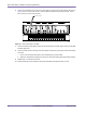
RF Rack Layout
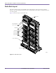
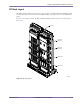
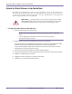
The RFSS modules slide into their respective slots and bolt to each RF shelf using #2 Phillips thumb
screws. In base stations that have less than 12 RFSS modules, the empty slots are covered with filler
panels.
Figure 4.9 shows the location of the RFSS modules and filler panels in a base station that supports
three sectors.
Figure 4.9
RF Rack Layout
00393
RF Rack
4-Slot RFSS
Filler Panel
2-Slot RFSS
Filler Panel
RFSS Module
00556
Cable Bracket