
User's Manual Part 1


58 Part ######A revision 00a-DRAFT March 29, 2006
Macro Base Station Installation Procedures (NPM-1000)
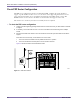
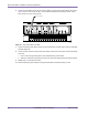
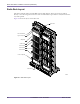
Figure 4.7
Main and Return Power Terminals
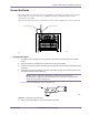
10 Ensure the main and return power cables are connected to the main power supply correctly by
performing a continuity test on each cable.
11 Dress and label the main and return power cables according to the standards and requirements of your
site.
NOTE: Ensure that the main and return power cables are tied in a manner that
minimizes the potential for creating electromagnetic fields. When tied together, the
main and return power cables should be arranged in an alternating order.
12 Repeat steps 1 to 9 for the second rack.
13 Reattach the rear cover to each rack’s PDP using four #2 Phillips screws. Torque each screw to 12
inch-pounds.
+24V/-48V Main Power
Terminals
Return Power
Terminals