
User's Manual Part 1


32 Part ######A revision 00a-DRAFT March 29, 2006
Macro Base Station Installation Procedures (NPM-1000)
Ground Riser Cable
The ground riser cable (the cable connecting the MGB to the building principal ground) must have a
minimum conductor sizing of 2/0 AWG. If any equipment cables at the site are larger than 2/0 AWG
(such as to compensate for voltage drop), the size of the ground riser cable must be adjusted. The
ground riser cable must use an equal or larger gauge than the largest conductor. The ground riser cable
must be labelled with a tag conforming to GR-1275-CORE.
In order for the ground riser cable to be nonrestrictive to lightning, the following guidelines should be
observed:
The cable should be run using the most direct route possible. The number and severity of
turns and bends should be minimized. Bends must not exceed 90°.
The cable must not be looped or coiled.
The cable must not be supported by metal clamps.
If a conduit is required to protect the cable, the conduit should be made of PVC. If a metal
conduit is used, the conduit must be bonded to the ground riser cable on both ends.
The cable must not run through or enter any metal boxes unless the boxes are bonded to the
ground riser cable at the entry and exit point.
Ground Resistance
The resistance of the building principal ground should be as low as practically possible (typically less
than 5
Ω). Under no circumstances should the resistance exceed the local electrical utility limits of 25Ω
(NEC article 250-56, 1999).
Ground Cable Fastening Techniques
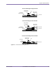
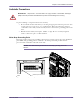
Figure 2.4 shows the correct methods for fastening the base station’s main grounds (one per rack) to a
master ground bar (MGB) (or other suitable grounding point).
If both main grounds from the base station racks are to be fastened to a single ground stud, the
grounds should be attached using the correct method shown in Figure 2.4. By using this method, the
ground from one rack can be removed without disturbing the ground for the other rack.