
User's Manual Part 1


March 29, 2006 Part ######A revision 00a-DRAFT 31
Chapter 2: Site Preparation
Antenna Mounting Locations
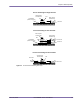
The base station uses two antennas (main and diversity) per sector. Ensure that your tower can support
the number of antennas shown in Table 2.18.
The field engineering package contains information about the size, weight, and installation
requirements of the antennas.
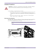
GPS Antenna Mounting Locations
The +24V version of the base station requires two 1-inch diameter hollow pipes for mounting the two
GPS antennas. The mounting location must be free of any objects that might block satellite visibility
within 10° of the horizon.
Cabling Requirements
Ensure that your site has the necessary cable racks and ladders to accommodate the base station and
that your site has external cable access ports for the GPS (+24V base stations only) and RF antenna
cabling. The field engineering package contains the cable layout specific to your site.
Isolated Ground Plane Environment
Ensure that the base station will be installed in an isolated ground plane environment as defined in
Telcordia Technologies GR-1275-CORE.
Master Ground Bar Requirements
The site’s master ground bar (MGB) must be connected to the building principal ground’s electrode
system. The building principal ground is the point where grounding conductors of the building (such
as air-conditioning, communication systems, and structure) are bonded together.
Ensure that the electrode system meets the requirements specified in the National Electrical Code
(NEC) article 250, sections 150–170, 1999.
NOTE: See the floor plan drawing in your field engineering package for the location
of the MGB.
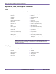
Supported Sectors Required Antennas
12
24
36
48
510
612
Table 2.18
Antenna Requirements