
User's Manual Part 1

26 Part ######A revision 00a-DRAFT March 29, 2006
Macro Base Station Installation Procedures (NPM-1000)
–48V Base Stations
The customer must ensure that base station site meets the requirements specified in this section.
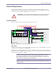
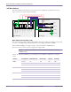
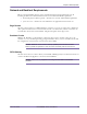
Figure 2.3 shows the power and ground cabling.
Figure 2.3
Base Station Power and Grounding Cabling
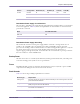
Base Station Power Supply (–48V)
The customer must provide a –48V (nominal) DC power supply capable of providing a voltage range
of –50V to –56V DC with maximum ripple/noise of 100 mVp-p from DC to 20 MHz.
The recommended DC power supply setting is –54.4V (measured at the PDP inputs).
For a six-sector base station, the power supply must supply 150A.
NOTE: A readily accessible disconnect device shall be incorporated in the building
installation wiring.
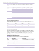
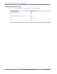
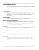
Table 2.14 shows the maximum power consumption for the different configurations of the base
station..
PDP
Base Station Rack Power Supply
Return 1
Return 2
Return 3
-48V Feed 3
-48V Feed 2
-48V Feed 1
Ground (PDP)
Ground (Frame)
Frame
-48V Bus
Return Bus
Ground Bus
Earth Ground
Circuit Breakers
Version Configuration Radio Rack (A) RF Rack (A) Total (A) Total (W)
MMDS 6 sectors 40 106 146 7305
3 sectors 24 55 79 3930
1 sectors 14 21 35 1765
WCS 6 sectors 40 106 146 7305
3 sectors 24 55 79 3930
1 sectors 14 21 35 1765
3.3 GHz 6 sectors 40 106 146 7425
3 sectors 24 55 79 3990
1 sectors 14 21 35 1785
Table 2.14
Power Consumption Values (–48V)