
User's Manual Part 1

24 Part ######A revision 00a-DRAFT March 29, 2006
Macro Base Station Installation Procedures (NPM-1000)
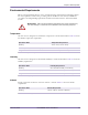
Table 2.9 shows the maximum power consumption for the different configurations of the base
station..
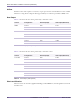
Main Power Bay Circuit Breaker Size
Each rack requires three +24V DC feeds. Table 2.11 shows the recommended values of the circuit
breakers to protect each feed.
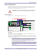
Main Power Source Grounding
The return lead (sometimes labeled as negative, "–") on the base station’s power supply shall be
connected to earth ground as close as possible to the +24V DC source (i.e. the rectifier or DC-DC
converter). For fault protection, the earthing conductor shall be sized in accordance with applicable
regulations to carry the full rated current of the 24V DC source. Since this is a positive-supply
negative-ground system, the return lead is the one with the most negative potential of the active
conductors, +24V and DC return.
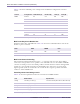
Power Bay Ground and Voltage Levels
Table 2.12 shows the required electrical levels as measured at the PDP terminals.
Version Configuration Radio Rack (A) RF Rack (A) Total (A) Total (W)
MMDS 6 sectors 80 212 292 7305
3 sectors 47 110 157 3930
1 sectors 28 42 71 1765
PCS 6 sectors 80 152 232 5805
3 sectors 49 80 129 3230
1 sectors 28 32 61 1515
WCS 6 sectors 80 212 292 7305
3 sectors 47 110 157 3930
1 sectors 28 42 71 1765
Table 2.10
Power Consumption Values (+24V)
Rack WCS MMDS PCS
Radio 70A 70A 70A
RF 100A 100A 70A
Table 2.11
Power Bay Circuit Breaker Sizes (+24V)
Unit Measurement Specification
Voltage +24V DC (+) to return (–) +27.0V DC nominal (25.0V DC min, 28.0V DC max)
Power +24V DC (+) to return (–) 10kW minimum
Voltage Return (–) to ground 0.5V DC maximum
Resistance Return (–) to ground 0.1Ω maximum
Voltage +24V DC (+) to ground +25.0V to +28.5V DC
Table 2.12
Required Ground Levels (+24V)