
User's Manual Part 1

22 Part ######A revision 00a-DRAFT March 29, 2006
Macro Base Station Installation Procedures (NPM-1000)
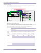
Airflow
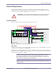
Each base station rack requires 0.6 m (2 feet) of open space in front of and behind it to allow suitable
airflow for cooling. Each cooling fan draws approximately 600 cubic feet per minute (CFM) of air.
Heat Output
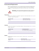
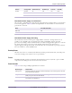
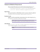
Table 2.9 shows the amount of heat produced by a +24V base station.
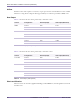
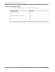
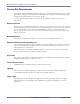
Table 2.9 shows the amount of heat produced by a –48V base station.
Shock and Vibration
The base station uses network equipment-building system (NEBS2000) racks designed for use in level
4 seismic zones.
Version Configuration Heat Output (W) Heat Output (BTU/hour)
MMDS 6 sectors 7065 24 107
3 sectors 3810 13 000
1 sectors 1725 5886
PCS 6 sectors 5565 18 989
3 sectors 3110 10 612
1 sectors 1475 5033
WCS 6 sectors 7005 23 902
3 sectors 3780 12 898
1 sectors 1715 5852
Table 2.8
Heat Output (+24V Systems)
Version Configuration Heat Output (W) Heat Output (BTU/hour)
3.3/3.5 GHz 6 sectors 7005 23 902
3 sectors 3780 12 898
1 sectors 1715 5852
MMDS 6 sectors 7065 24 107
3 sectors 3810 13 000
1 sectors 1725 5886
WCS 6 sectors 7005 23 902
3 sectors 3780 12 898
1 sectors 1715 5852
Table 2.9
Heat Output (–48V Systems)