Macro Base Station Installation Procedures (NPM-1000) Release 2.
Copyright 2006 SOMA Networks, Inc. SOMA Networks, Inc. 185 Berry Street Suite 4600 San Francisco, CA 94107 U.S.A. Phone +1.415.882.6500 Fax +1.415.882.6501 SOMA, SOMA Networks and the star-and-circle design are trademarks or registered trademarks of SOMA Networks, Inc in the United States and other countries. All SOMA Networks product names are trademarks of SOMA Networks, Inc. All other company and product names may be trademarks or registered trademarks of their respective owners.
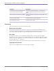
P REFACE Chapter 0 This book explains how to install a SOMA NPM-1000 macro base station. Installation includes installing the racks, connecting the base station to the network core, and powering on the system. This book is intended for field technicians with experience installing and configuring telecommunications equipment at cellular base stations and network operations centers. Related Documentation SOMA Documentation Suite Table 1 shows the guides in the SOMA service provider documentation suite.
Macro Base Station Installation Procedures (NPM-1000) Document Description Central Office Environment Installation/Removal Generic Requirements (GR-1275-CORE) Available from Telcordia Technologies, Inc. Provides generic installation requirements for telecommunication suppliers and carriers. Zyfer AccuSync-R GPS Synchronized Time and Frequency Instrument User’s Manual (377-8006) Available from Zyfer, Inc.
Preface Font Usage Example Courier System output and all things involving source code (commands, samples, methods, functions, objects, variables, types, constants, fields, properties, and structures) echo “NETWORKING=yes HOSTNAME=soma Courier bold User-keyed commands eject cdrom ↵ Arial gray Interface objects: buttons, links, fields, and drop-down list names Click OK.
Macro Base Station Installation Procedures (NPM-1000) W A R N I N G : A general warning is shown when there is a risk of personal injury from ! a nonelectrical hazard or a risk of irreversible damage to data, software, or the operating system. W A R N I N G : An electrical warning is shown when there is danger of physical harm to a person or damage to equipment due to electrical hazard. Document Change History Table 5 shows the change history for this document.
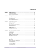
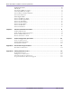
CONTENTS Chapter 1 Installation Overview......................................................................................................... 13 Installation Process Summary . . . . . . . . . . . . . . . . . . . . . . . . . . . . . . . . . . . . . . . . . . . . . . . . . . . . . . . 14 Necessary Conditions for Installation . . . . . . . . . . . . . . . . . . . . . . . . . . . . . . . . . . . . . . . . . . . . . . . . . 15 Chapter 2 Site Preparation ....................................................
Macro Base Station Installation Procedures (NPM-1000) Chapter 5 Populating the Shelves....................................................................................................................... Shelf Layout . . . . . . . . . . . . . . . . . . . . . . . . . . . . . . . . . . . . . . . . . . . . . . . . . . . . . . . . . . . . . . . . . . . . . Insert CompactPCI Power Supplies . . . . . . . . . . . . . . . . . . . . . . . . . . . . . . . . . . . . . . . . . . . . . . . . . . .
LIST OF TABLES Chapter 1 Installation Overview Table 1.1 Installation Process Summary. . . . . . . . . . . . . . . . . . . . . . . . . . . . . . . . . . . . . . . . . . . . . . . . . . . . . . . . . . . . 14 Chapter 2 Site Preparation Table 2.1 Table 2.2 Table 2.3 Table 2.4 Table 2.5 Table 2.6 Table 2.7 Table 2.8 Table 2.9 Table 2.10 Table 2.11 Table 2.14 Table 2.15 Rack Dimensions. . . . . . . . . . . . . . . . . . . . . . . . . . . . . . . . . . . . . . . . . . . . . . . . . . . . . . . . . . . . .
Macro Base Station Installation Procedures (NPM-1000) 10 Part ######A revision 00a-DRAFT March 29, 2006
LIST OF FIGURES Chapter 1 Installation Overview Chapter 2 Site Preparation Figure 2.1 Figure 2.2 Figure 2.3 Figure 2.4 Rack Dimensions . . . . . . . . . . . . . . . . . . . . . . . . . . . . . . . . . . . . . . . . . . . . . . . . . . . . . . . . . . . . . . . . . . . . 18 Base Station Power and Ground Cabling . . . . . . . . . . . . . . . . . . . . . . . . . . . . . . . . . . . . . . . . . . . . . . . . . . 23 Base Station Power and Grounding Cabling . . . . . . . . . . . . . . . . . . . . . . . . . .
Macro Base Station Installation Procedures (NPM-1000) 12 Part ######A revision 00a-DRAFT March 29, 2006
Chapter 1 I NSTALLATION OVERVIEW Chapter 1 This chapter provides an overview of the installation process. Please familiarize yourself with the installation process in general before proceeding to the next chapter. Contents Installation Process Summary ...................................................................................................................... 14 Necessary Conditions for Installation .................................................................................................
Macro Base Station Installation Procedures (NPM-1000) Installation Process Summary Installation of the NPM-1000 SOMA macro base station should take approximately two to three days, assuming the site already meets the requirements specified in Chapter 2, “Site Preparation”. Three people should be present during the installation, especially when moving base station equipment. Table 1.1 lists the procedures to install the base station.
Chapter 1: Installation Overview Necessary Conditions for Installation The installation procedures in this manual assume that the following conditions have been met: The core servers located at the network operations center (NOC) are operational A backhaul connection between the base station site and NOC is installed. The backhaul has been tested and is connected to the site’s edge router.
Macro Base Station Installation Procedures (NPM-1000) 16 Part ######A revision 00a-DRAFT March 29, 2006
Chapter 2 SITE PREPARATION Chapter 2 This chapter identifies the requirements that your site needs to meet before you can proceed with the installation of the base station. Please review these requirements before proceeding to the next chapter. Contents Physical Requirements ................................................................................................................................. Environmental Requirements ............................................................................
Macro Base Station Installation Procedures (NPM-1000) Physical Requirements Before you begin installing the base station, read the following physical requirements. Ensure that each requirement is met before proceeding with the installation, and consult your methods of procedures (MOPs) for information concerning transportation method, route, and precise installation location.
Chapter 2: Site Preparation Weight A dolly or crane is required to move the racks. Table 2.2 shows the weight of the major components. Component WCS MMDS PCS 3.3/3.5 GHz Empty single rack 70.3 kg (155 pounds) 70.3 kg (155 pounds) 70.3 kg (155 pounds) 70.3 kg (155 pounds) RF rack, filled to capacity 331.1 kg (730 pounds) 346 kg (762 pounds) 291 kg (642 pounds) 346 kg (762 pounds) Radio rack, filled to capacity 207.3 kg (457 pounds) 207.3 kg (457 pounds) 207.3 kg (457 pounds) 207.
Macro Base Station Installation Procedures (NPM-1000) Torque Values Table 2.4 shows the recommended torque values for the different sizes of fasteners used in the racks. Unless otherwise specified, torque tolerances are ±2 inch-pounds. Fastener Size Recommended Torque Fastener Size Recommended Torque #4 (0.112-inch) screw 6 inch-pounds SMA connector 5 inch-pounds #6 (0.138-inch) screw 12 inch-pounds Type-N connector 12 inch-pounds #8 (0.
Chapter 2: Site Preparation Environmental Requirements Before you begin installing the base station, read the following environmental requirements. Ensure that each requirement is met before proceeding with the installation and consult your MOPs for procedures concerning building requirements, hazardous materials and waste, and environmental systems.
Macro Base Station Installation Procedures (NPM-1000) Airflow Each base station rack requires 0.6 m (2 feet) of open space in front of and behind it to allow suitable airflow for cooling. Each cooling fan draws approximately 600 cubic feet per minute (CFM) of air. Heat Output Table 2.9 shows the amount of heat produced by a +24V base station.
Chapter 2: Site Preparation Electrical Requirements Before you begin installing the base station, read the following requirements. Ensure that each requirement is met before proceeding with the installation and consult your MOPs for procedures concerning power, grounding, and high-risk cut-over activities. W A R N I N G : Failure to meet the following requirements may result in personal injury and cause damage to or destruction of the base station and surrounding equipment. ! +24V Base Stations Figure 2.
Macro Base Station Installation Procedures (NPM-1000) Table 2.9 shows the maximum power consumption for the different configurations of the base station..
Chapter 2: Site Preparation Base Station Circuit Breaker Current Loads Each rack contains a power distribution panel (PDP). The PDP has up to 16 circuit breakers (CBs). Each breaker switch controls the power to a specific component. Individual components can be powered off by setting the appropriate breaker switch to the OFF (down) position. Table 2.13 shows the maximum current loading of the circuit breakers in the RFSS and radio rack PDPs.
Macro Base Station Installation Procedures (NPM-1000) –48V Base Stations The customer must ensure that base station site meets the requirements specified in this section. Figure 2.3 shows the power and ground cabling. Circuit Breakers PDP -48V Bus Return Bus Return 1 Return 2 Return 3 -48V Feed 3 -48V Feed 2 -48V Feed 1 Ground (PDP) Ground (Frame) Frame Ground Bus Earth Ground Base Station Rack Figure 2.
Chapter 2: Site Preparation Version Configuration Radio Rack (A) RF Rack (A) Total (A) Total (W) 3.5 GHz 6 sectors 40 106 146 7425 3 sectors 24 55 79 3990 1 sectors 14 21 35 1785 Table 2.14 Power Consumption Values (–48V) Base Station Power Supply Circuit Breakers The customer’s –48V DC power supply must be equipped with six circuit breakers to power the base station rack equipment. Table 2.15 shows the required sizes of circuit breakers on each of the three power feeds to each rack.
Macro Base Station Installation Procedures (NPM-1000) Compression Lug Color Codes Table 2.17 shows the compression lug color codes for common wire gauges. Wire Gauge (AWG) Color Code #6 (used for ground cables) Blue #4 Gray #2 (used for main and return power cables) Brown #1 Green 1/0 Pink 2/0 Blank Table 2.
Chapter 2: Site Preparation Network and Backhaul Requirements Before you begin installing the base station, read the following network requirements.
Macro Base Station Installation Procedures (NPM-1000) General Site Requirements Each site has unique requirements and characteristics. See your field engineering package for specific requirements relating to your installation. The field deployment package contains the site’s floor plan, cabling routing and termination, and other site-specific See the Network Deployment Planning Guide for a comprehensive description of generic site requirements.
Chapter 2: Site Preparation Antenna Mounting Locations The base station uses two antennas (main and diversity) per sector. Ensure that your tower can support the number of antennas shown in Table 2.18. Supported Sectors Required Antennas 1 2 2 4 3 6 4 8 5 10 6 12 Table 2.18 Antenna Requirements The field engineering package contains information about the size, weight, and installation requirements of the antennas.
Macro Base Station Installation Procedures (NPM-1000) Ground Riser Cable The ground riser cable (the cable connecting the MGB to the building principal ground) must have a minimum conductor sizing of 2/0 AWG. If any equipment cables at the site are larger than 2/0 AWG (such as to compensate for voltage drop), the size of the ground riser cable must be adjusted. The ground riser cable must use an equal or larger gauge than the largest conductor.
Chapter 2: Site Preparation Correct Fastening for Single Ground Sole Purpose Ground Stud Nut Ring Tongue Terminal Lug Lockwasher (tooth if on paint) Ground A Correct Fastening for Two Grounds Sole Purpose Ground Stud Ring Tongue Terminal Lug Nut Lockwasher (tooth if on paint) Ground B Ground A Incorrect Fastening for Two Grounds Sole Purpose Ground Stud Ground B Nut Ground A Figure 2.
Macro Base Station Installation Procedures (NPM-1000) 34 Part ######A revision 00a-DRAFT March 29, 2006
Chapter 3 PRE-INSTALLATION PROCEDURES Chapter 3 This chapter lists the tools and equipment required for installing and testing the base station. It also provides procedures for unpacking the racks and configuring individual cards and shelves. Contents Preparing for Installation ............................................................................................................................... Antistatic Precautions ...............................................................................
Macro Base Station Installation Procedures (NPM-1000) PREPARING FOR INSTALLATION This section describes precautions, equipment, and tasks that should be reviewed or performed prior to beginning the installation.
Chapter 3: Pre-Installation Procedures Antistatic Precautions W A R N I N G : Components in the base station are highly sensitive to electrostatic discharges (ESD). Follow the procedures described below to prevent unseen damage from occurring. To prevent damage to components from static electricity: Do not handle circuit boards unless you are using the appropriate antistatic protection, such as wrist straps, boot straps, boots, or a conductive mat.
Macro Base Station Installation Procedures (NPM-1000) Equipment, Tools, and Supplies Checklists Tools The following tools are recommended for a typical base station installation: Allen key set Platform stepladder (6-foot) Bolt cutter Plumb bob Cable ties Portable bandsaw kit Chalk line Scissors Drill bits (metal and masonry) Scratch awl Electrical tape Shims (for leveling racks) Extension cord Socket sets (Imperial and metric) Flat file Strap (with buckle)
Chapter 3: Pre-Installation Procedures Test Equipment Table 3.1 shows the equipment recommended for testing base station functionality.
Macro Base Station Installation Procedures (NPM-1000) Unpack the Equipment The racks are delivered on shipping pallets. Each rack is secured in an upright position and is bolted to the pallet. Additional equipment is delivered in separate shipping boxes. To unpack the base station equipment 1 Transport the shipping boxes to the installation area using a dolly or pallet jack. 2 Inspect the exterior packaging for any noticeable damage that may have occurred during shipment.
Chapter 3: Pre-Installation Procedures Review Site Deliverables List Table 3.3 shows the paperwork that ships with each base station. Document Description Anchor kit Lists installation kit contents BOM Lists every component in the base station Shelf inspection checklist Factory inspection of each utility and radio shelf Table 3.3 Inventory Checklists To check the inventory 1 Perform an inventory check using the site deliverables list provided with the E1 package and BOMs.
Macro Base Station Installation Procedures (NPM-1000) CONFIGURING CARDS The base station can use a variety of third-party, off-the-shelf processor and Ethernet cards. The jumpers and switches on the cards may require configurations which differ from the factory defaults. This section provides the procedures for making the necessary alterations. N O T E : Consult your field engineering package for information about the type, number, and configuration of cards used in your base station.
Chapter 3: Pre-Installation Procedures CPC4400 Ethernet Switch The CPC4400 is used for the base station’s Ethernet switches. It may be necessary to modify the jumpers, as the base station uses a configuration of the Ethernet switches that differs from the manufacturer’s original settings. N O T E : If the Ethernet switches are pre-installed in the shelves, then they have already been configured and this procedure is not required. Table 3.4 shows the correct settings of the Ethernet switch jumpers.
Macro Base Station Installation Procedures (NPM-1000) K1 PCI Reset Jumper K7 CPCI BDSEL 00275 Figure 3.2 3 44 CPC4400 Jumper Configuration Place the cards back in their antistatic packaging until you are ready to install them in the shelves.
Chapter 3: Pre-Installation Procedures Concurrent 310 Processor Card The Concurrent 310 is used for both the radio sector controllers and utility bus controllers. It may be necessary to modify the BIOS and jumper settings, as the base station uses a configuration of these cards that differs from the manufacturer’s original settings. N O T E : If the cards are pre-installed in the shelves, then they have already been configured and this procedure is not required. BIOS Settings Table 3.
Macro Base Station Installation Procedures (NPM-1000) To configure the Concurrent 310 cards 1 Remove cards from their antistatic packaging at a grounded work area. Ensure that you are properly grounded with a wrist or boot strap before handling the cards. Depending on the configuration of your base station, you may have up to eight cards that need to be configured. 2 Ensure that the card’s BIOS settings are correct. 3 Ensure that the jumper switches are configured as shown in Table 3.6. Figure 3.
Chapter 4 BASE STATION INSTALLATION PROCEDURES Chapter 4 This chapter provides procedures for installing the racks and their internal components. Before proceeding with this chapter, you must complete all the tasks described in Chapter 3. Contents Installing the Racks ....................................................................................................................................... Prepare the Location ...................................................................................
Macro Base Station Installation Procedures (NPM-1000) INSTALLING THE RACKS These procedures describe how to prepare the floor for rack installation, move the racks into place, and secure the racks to each other, to the floor, and to the ceiling. Procedure Page Prepare the Location 49 Position the Racks 50 Secure the Racks 51 N O T E : When you install the racks, finish positioning and leveling the first rack before proceeding to the second rack.
Chapter 4: Base Station Installation Procedures Prepare the Location This procedure applies to installing the base station on a concrete floor and securing the racks using 4-inch concrete expansion bolts (called anchor bolts in this document). These anchor bolts are designed for sites in level 4 seismic zones and may not be suitable for your site. See your field engineering package for rack installation procedures specific to your site.
Macro Base Station Installation Procedures (NPM-1000) Position the Racks This procedure describes how to position and level the racks. To position the racks 1 Install two eyelet bolts in the top of each rack if you intend to use a crane to move the racks. 2 If you are using anchor bolts, remove the tape from the anchor holes. 3 Place the isolation pad back in the precise location designated for the rack using the chalk line and optional drilled holes as your guide.
Chapter 4: Base Station Installation Procedures Secure the Racks This procedure describes how to secure the radio and RF racks in place. The racks may be secured to the ground, to the ceiling, and to each other. Figure 4.2 shows the location of the junction bar and the support bolt holes. Support Bolt Holes Junction Bar 00554 Figure 4.2 Junction Bar and Support Bolt Hole Locations To secure the racks 1 Ensure that the racks are correctly positioned and vertically aligned.
Macro Base Station Installation Procedures (NPM-1000) 52 ix Tighten the four anchor bolts in the base of each rack by turning the 3/4-inch washer nut while holding the 1/4-inch anchor bolt in place. The expansion sleeve is forced open, which secures the rack to the floor. x Reattach the lower cooling units to each frame using the 5/16-inch screws. Torque the screws to 50 inch-pounds. xi Reattach the front grill to each frame using the grill’s two half-turn screws.
Chapter 4: Base Station Installation Procedures ATTACHING GROUND AND POWER CABLES These procedures describe how to ground and power the base station. Procedure Page Check PDP Sector Configuration 54 Ground the Racks 55 Attach the Main and Return Power Cables 57 W A R N I N G : Ensure that all of the circuit breakers on each power distribution panel (PDP) are in the OFF (down) position before attaching any cables.
Macro Base Station Installation Procedures (NPM-1000) Check PDP Sector Configuration The PDP sector configuration switch, located inside the PDP, configures the circuit breakers to support a specific number of radio sectors (1–6). In a base station supporting fewer than six sectors, some of the circuit breakers are not used and are therefore left in the OFF (down) position. The OAMP software uses the switch to determine if a circuit breaker has tripped or is not used.
Chapter 4: Base Station Installation Procedures Ground the Racks Each rack requires a ground cable connecting the PDP to the building’s grounding system. A frame ground cable connects the rack’s frame to the PDP, ensuring that the frame and its attached components are grounded. Figure 4.4 shows the cables used to ground the racks. For clarity, the PDP rear cover is not depicted. Frame Ground Cable Main Ground Cable 00279 Figure 4.
Macro Base Station Installation Procedures (NPM-1000) 6 Connect the compression lug on the main ground cable to one of the two ground terminals, as shown in Figure 4.6. Use a 1/4-inch hex nut with a 1/4-inch split-lock washer when securing the cable. Torque each 1/4-inch hex nut to 78 inch-pounds. Ground Terminals 00281 Figure 4.6 Ground Terminals on the PDP 7 Connect the frame ground cable to the second ground terminal on the PDP using a minimum of #6 AWG stranded copper wire.
Chapter 4: Base Station Installation Procedures Attach the Main and Return Power Cables Refer to the MOPs before scheduling or beginning any work involving the site’s main power. Before proceeding with this procedure, ensure that all the necessary site cable layout, runaway, and grid work has been completed. W A R N I N G : Ensure that the necessary requirements and procedures have been reviewed prior to the start of any power-related activity.
Macro Base Station Installation Procedures (NPM-1000) +24V/-48V Main Power Terminals Figure 4.7 Return Power Terminals Main and Return Power Terminals 10 Ensure the main and return power cables are connected to the main power supply correctly by performing a continuity test on each cable. 11 Dress and label the main and return power cables according to the standards and requirements of your site.
Chapter 4: Base Station Installation Procedures ATTACHING THE SHELVES AND MODULES These procedures describe how to attach the shelves and modules to the racks.
Macro Base Station Installation Procedures (NPM-1000) Radio Rack Layout The utility and radio shelves and the GPS clock module slide into their respective bays and bolt directly to the rack using 5/16-inch screws. The recommended torque value for each 5/16-inch screw is 50 inch-pounds. Figure 4.8 shows the layout of the radio rack. Radio Rack GPS Clock Module Upper Cooling Unit Utility Shelf Cable Trough Radio Shelf #2 Radio Shelf #1 Radio Shelf #0 Lower Cooling Unit Cable Bracket 00393 Figure 4.
Chapter 4: Base Station Installation Procedures RF Rack Layout The RFSS modules slide into their respective slots and bolt to each RF shelf using #2 Phillips thumb screws. In base stations that have less than 12 RFSS modules, the empty slots are covered with filler panels. Figure 4.9 shows the location of the RFSS modules and filler panels in a base station that supports three sectors. RF Rack 4-Slot RFSS Filler Panel 2-Slot RFSS Filler Panel Cable Bracket RFSS Module 00393 Figure 4.
Macro Base Station Installation Procedures (NPM-1000) Attach the Radio Shelves to the Radio Rack Depending on the configuration of your base station, there may be one, two, or three radio shelves that need to be installed. The radio shelves are installed in the bottom three bays in the radio rack. If your base station uses fewer than three radio shelves, you need to add filler shelves to the empty bays to ensure the required airflow to the occupied bays.
Chapter 4: Base Station Installation Procedures Cover Empty Radio Bays Depending on the configuration of your base station, there may be empty bays on the radio rack. Your base station may arrive with the unused radio bays already occupied with filler shelves. If this is not the case or if the configuration of your base station has changed, you need to add filler shelves to any empty bays to ensure the required airflow to the occupied bays.