
User Manual


December 16, 2002 Part 003609A revision 01 121
Chapter 6: On-Site Software Installation and Configuration Procedures
To optimize the GPS clock module
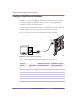
1 Connect a PC to the GPS clock module using a custom adapter and a standard
serial cable.
NOTE: Using a standard serial or null modem cable without a
custom adapter will not work.
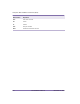
2 Start a serial terminal session using the settings shown in Table 6.1.
NOTE: See the Amosphere NPM Maintenance Procedures for
additional information about connecting a serial terminal to the
GPS clock module.
3 Calculate the cable delay by multiplying the total cable length by the delay value.
For example, if the delay value of the cable is 4.36 ns/m and there is 15 m of
cable, then the cable delay would be 15 m x 4.36 ns/m = 65.4 ns. Round the result
to the nearest nanosecond. In this case, the result would be 65 ns.
4 Set the cable delay for the first GPS plug-in module. This example uses a cable
delay of 65 ns. Replace the 65 in the following command with your own calculated
cable delay value:
$ANT1,65*
↵
5 Set the cable delay for the second GPS plug-in module. Again, replace the 65 in
the following command with your own calculated cable delay value:
$ANT2,65*
↵
The GPS clock module briefly enters coasting mode as it recalculates its position.
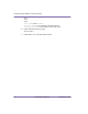
Parameter Setting
Baud 9600 bits/s
Data bits 8
Parity None
Stop bits 1
Flow control None
ASCII setup Send linefeeds, local character echo on
Table 6.1
GPS Clock Module Serial Port Settings