
User Manual

December 16, 2002 Part 003609A revision 01 117
Chapter 5: Power-On Procedures
4 Power on the GPS clock module by setting CB 15 to the ON (up) position.
The GPS clock module will perform its internal diagnostics and begin to acquire
and track satellites. It may take up to 30 min for the GPS receivers to acquire a
rough position and time. The accuracy of the receivers improves as the satellites
are tracked.
See AccuSync-R GPS Synchronized Time and Frequency Instrument User’s
Manual (377-8006), available from Zyfer Inc., for information about the GPS clock
module.
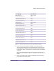
5 Power on each RFSS module in the RF rack separately. Table 5.2 shows the
circuit breakers for the RFSS modules.
Power Supply Circuit Breaker
Bottom radio shelf,
left power supply (slots 0–1)
Radio rack PDP,
CB 02
Bottom radio shelf,
middle power supply (slots 2–3)
Radio rack PDP,
CB 03
Bottom radio shelf,
right power supply (slots 4–5)
Radio rack PDP,
CB 04
Middle radio shelf,
left power supply (slots 0–1)
Radio rack PDP,
CB 05
Middle radio shelf,
middle power supply (slots 2–3)
Radio rack PDP,
CB 06
Middle radio shelf,
right power supply (slots 4–5)
Radio rack PDP,
CB 07
Top radio shelf,
left power supply (slots 0–1)
Radio rack PDP,
CB 08
Top radio shelf,
middle power supply (slots 2–3)
Radio rack PDP,
CB 09
Top radio shelf,
right power supply (slots 4–5)
Radio rack PDP,
CB 10
Utility shelf,
left power supply (slots 0–1)
Radio rack PDP,
CB 11
Utility shelf,
middle power supply (slots 2–3)
Radio rack PDP,
CB 12
Utility shelf,
right power supply (slots 4–5)
Radio rack PDP,
CB 13
Table 5.1
Utility and Radio Shelf Power Supply Circuit Breaker Summary