
User Manual


100 Part 003609A revision 01 December 16, 2002
Amosphere NPM Installation Procedures (WCS)
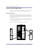
Connect the Alarm Cables
The alarm cables are serial cables with DSUB connectors on each end. The
DSUB connectors are secured to their receptacles with 1/8-inch flathead screws.
To connect the alarm cables
1 Ensure that the main +24V DC power supply is powered off.
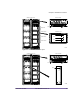
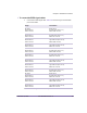
2 Connect the alarm cables to the alarm wiring card. Table 4.14 shows the origin
and termination point of each cable.
3 Connect any custom I/O cables. See your E1 package for details.
WARNING: Ensure that the main +24V DC power supply for the NPM is
powered off before connecting the alarm cables. The PDP alarm cables are
hot at all times and are not hot-swappable, even when the circuit breakers in
the PDP are powered OFF (down). Failure to power off the main +24V DC
power supply may result in damage to the cables and NPM.
Origin Termination
Alarm wiring card (slots 12–13),
UPPER COOLING RF connector
RF rack, upper cooling unit,
SIGNAL connector
Alarm wiring card (slots 12–13),
UPPER COOLING RADIO connector
Radio rack, upper cooling unit,
SIGNAL connector
Alarm wiring card (slots 12–13),
LOWER COOLING RF connector
RF rack, lower cooling unit,
SIGNAL connector
Alarm wiring card (slots 12–13),
LOWER COOLING RADIO connector
Radio rack, lower cooling unit,
SIGNAL connector
Alarm wiring card (slots 12–13),
RF PDP connector
RF rack, PDP SGNL connector
(left-most connector)
Alarm wiring card (slots 12–13),
RADIO PDP connector
Radio rack, PDP SGNL connector
(left-most connector)
Table 4.14
Alarm Cable Summary