
User Manual


December 16, 2002 Part 003609A revision 01 99
Chapter 4: Installation Procedures
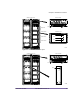
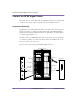
To connect the RFSS signal cables
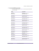
1 Connect each RFSS signal cable. Table 4.13 shows the origin and termination
point of each cable.
Origin Termination
RF shelf 0,
RFSS module 0,
SGNL connector
Radio shelf 0,
left IF/RF card (slots 10–11),
SGNL MAIN connector
RF shelf 0,
RFSS module 1,
SGNL connector
Radio shelf 0,
left IF/RF card (slots 10–11),
SGNL DIV connector
RF shelf 0,
RFSS module 2,
SGNL connector
Radio shelf 0,
right IF/RF card (slots 15–16),
SGNL MAIN connector
RF shelf 0,
RFSS module 3,
SGNL connector
Radio shelf 0,
right IF/RF card (slots 15–16),
SGNL DIV connector
RF shelf 1,
RFSS module 0,
SGNL connector
Radio shelf 1,
left IF/RF card (slots 10–11),
SGNL MAIN connector
RF shelf 1,
RFSS module 1,
SGNL connector
Radio shelf 1,
left IF/RF card (slots 10–11),
SGNL DIV connector
RF shelf 1,
RFSS module 2,
SGNL connector
Radio shelf 1,
right IF/RF card (slots 15–16),
SGNL MAIN connector
RF shelf 1,
RFSS module 3,
SGNL connector
Radio shelf 1,
right IF/RF card (slots 15–16),
SGNL DIV connector
RF shelf 2,
RFSS module 0,
SGNL connector
Radio shelf 2,
left IF/RF card (slots 10–11),
SGNL MAIN connector
RF shelf 2,
RFSS module 1,
SGNL connector
Radio shelf 2,
left IF/RF card (slots 10–11),
SGNL DIV connector
RF shelf 2,
RFSS module 2,
SGNL connector
Radio shelf 2,
right IF/RF card (slots 15–16),
SGNL MAIN connector
RF shelf 2,
RFSS module 3,
SGNL connector
Radio shelf 2,
right IF/RF card (slots 15–16),
SGNL DIV connector
Table 4.13
RFSS Signal Cable Summary