
User Manual

88 Part 003609A revision 01 December 16, 2002
Amosphere NPM Installation Procedures (WCS)
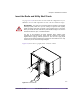
3 Power off all the power supplies in the radio and utility shelves.
4 Power off your main +24V DC power supply.
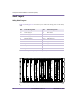
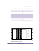
Power Supply Circuit Breaker
Radio shelf #0 (bottom), left power supply (slots 0–1) Radio rack PDP, CB 02
Radio shelf #0 (bottom), middle power supply (slots 2–3) Radio rack PDP, CB 03
Radio shelf #0 (bottom), right power supply (slots 4–5) Radio rack PDP, CB 04
Radio shelf #1 (middle), left power supply (slots 0–1) Radio rack PDP, CB 05
Radio shelf #1 (middle), middle power supply (slots 2–3) Radio rack PDP, CB 06
Radio shelf #1 (middle), right power supply (slots 4–5) Radio rack PDP, CB 07
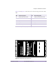
Radio shelf #2 (top), left power supply (slots 0–1) Radio rack PDP, CB 08
Radio shelf #2 (top), middle power supply (slots 2–3) Radio rack PDP, CB 09
Radio shelf #2 (top), right power supply (slots 4–5) Radio rack PDP, CB 10
Utility shelf, left power supply (slots 0–1) Radio rack PDP, CB 11
Utility shelf, middle power supply (slots 2–3) Radio rack PDP, CB 12
Utility shelf, right power supply (slots 4–5) Radio rack PDP, CB 13
Table 4.9
Utility and Radio Shelf Power Supply Circuit Breaker Summary