
User Manual

December 16, 2002 Part 003609A revision 01 83
Chapter 4: Installation Procedures
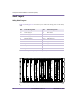
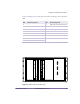
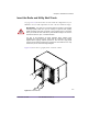
Table 4.6 and Figure 4.12 show the layout of the rear-facing cards on the utility
shelf.
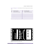
Figure 4.12
Utility Shelf Layout (Rear View)
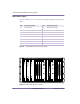
Slot Rear-Facing Card Slot Rear-Facing Card
6–7 Ethernet switch rear I/O card 14 Utility bus controller rear I/O card
8— 15—
9 Application host rear I/O card 16 —
10 Utility bus controller rear I/O card 17 Application host rear I/O card
11 Application host rear I/O card 18 Application host rear I/O card
12–13 Alarm wiring card 19–20 Ethernet switch rear I/O card
Table 4.6
Utility Shelf Layout (Rear-Facing Cards)
00285
20-19 18 14 13-12 11 10 9 8 7-617 16 15