
User Manual

82 Part 003609A revision 01 December 16, 2002
Amosphere NPM Installation Procedures (WCS)
Shelf Layout
Utility Shelf Layout
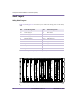
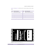
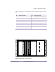
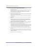
Table 4.5 and Figure 4.11 show the layout of the front-facing cards on the utility
shelf.
Figure 4.11
Utility Shelf Layout (Front View)
Slot Front-Facing Card Slot Front-Facing Card
0–1 Power supply 0 12 Alarm card 0
2–3 Power supply 1 13 Alarm card 1
4–5 Power supply 2 14 Utility bus controller 1
6 Ethernet switch 0 15–16 Hard disk drive 1
7–8 Hard disk drive 0 17 Application host 3
9 Application host 0 18 Application host 1
10 Utility bus controller 0 19 Ethernet switch 1
11 Application host 2 20 —
Table 4.5
Utility Shelf Layout (Front-Facing Cards)
00390
0-1 2-3 4-5 6 7-8 9 10 11 12 13 14 15-16
17
19 20
HDD
Activity
SCSI
Activity
HDD
Activity
SCSI
Activity
18
POWER GOOD
INPUT
OUTPUT
POWER GOOD
INPUT
OUTPUT
POWER GOOD
INPUT
OUTPUT
HDD
Activity
SCSI
Activity
HDD
Activity
SCSI
Activity
POWER GOOD
INPUT
OUTPUT