Chapter 4: Installation Procedures ATTACHING THE SHELVES AND MODULES These procedures describe how to attach the shelves and modules to the NPM racks. Table 4.3 shows the actions described in this section. Action Page Attach the Radio Shelves to the Radio Rack 74 Cover Empty Radio Bays 75 Attach the Utility Shelf to the Radio Rack 76 Install the GPS Clock Module 77 Install the RFSS Modules 78 Cover Empty RFSS Slots 79 Table 4.
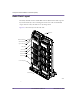
Amosphere NPM Installation Procedures (WCS) Radio Rack Layout The utility and radio shelves and the GPS clock module slide into their respective bays and bolt directly to the rack using 5/16-inch screws. The recommended torque value for each 5/16-inch screw is 50 inch-pounds. Figure 4.9 shows the layout of the radio rack.
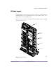
Chapter 4: Installation Procedures RF Rack Layout The RFSS modules slide into their respective slots and bolt to each RF shelf using #2 Phillips thumb screws. In NPMs that have less than 12 RFSS modules, the empty slots are covered with filler panels. Figure 4.10 shows the location of the RFSS modules and filler panels in an NPM that supports three sectors. RF Rack 4-Slot RFSS Filler Panel 2-Slot RFSS Filler Panel Cable Bracket RFSS Module 00393 00447 Figure 4.
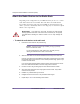
Amosphere NPM Installation Procedures (WCS) Attach the Radio Shelves to the Radio Rack Depending on the configuration of your NPM, there may be one, two, or three radio shelves that need to be installed. The radio shelves are installed in the bottom three bays in the radio rack. If your NPM uses fewer than three radio shelves, you need to add dummy shelves to the empty bays to ensure the required airflow to the occupied bays.
Chapter 4: Installation Procedures Cover Empty Radio Bays Depending on the configuration of your NPM, there may be empty bays on the radio rack. Your NPM may arrive with the unused radio bays already occupied with dummy shelves. If this is not the case or if the configuration of your NPM has changed, you need to add dummy shelves to any empty bays to ensure the required airflow to the occupied bays.
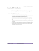
Amosphere NPM Installation Procedures (WCS) Attach the Utility Shelf to the Radio Rack The utility shelf is installed in the top-most bay in the radio rack. To attach the utility shelf to the radio rack 1 Remove the utility shelf from its protective bag. You can distinguish the utility shelf from the radio shelves by reading the manufacturer’s label on the inside of the chassis. 2 Slide the utility shelf into the top bay in the radio rack.
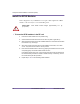
Chapter 4: Installation Procedures Install the GPS Clock Module The Global Positioning System (GPS) clock module consists of a 1U module that contains two plug-in GPS receivers. The GPS clock module requires two GPS antennas. GPS antenna installation is described on page 110. To install the GPS clock module 1 Remove the GPS clock module from its antistatic packaging.
Amosphere NPM Installation Procedures (WCS) Install the RFSS Modules If the configuration of your NPM does not require a full complement of RFSS modules, some slots may be covered with filler panels. CAUTION: Each RFSS module weighs approximately 14.1 kg (31 pounds). ! To insert the RFSS modules in the RF rack 1 Remove the RFSS module from its protective bag. 2 Orient the RFSS module so that the text on the front panel is right-side up. 3 Slide the RFSS module into the first available RFSS slot.
Chapter 4: Installation Procedures Cover Empty RFSS Slots Any empty slots in the RF shelves should be covered with RFSS filler panels. The RFSS filler panels protect the other RFSS modules from dust and ensure the required air flow to the installed RFSS modules. To cover unused slots with RFSS filler panels 1 Remove the RFSS filler panel from its protective bag. 2 Orient the filler panel so that the text on the front panel is right-side up.
Amosphere NPM Installation Procedures (WCS) 80 Part 003609A revision 01 December 16, 2002
Chapter 4: Installation Procedures POPULATING THE SHELVES These procedures describe how to install the CompactPCI power supplies and cards into the utility and radio shelves. Table 4.4 lists the actions described in this section. Action Page Insert CompactPCI Power Supplies 86 Test CompactPCI Power Supplies 87 Insert the Radio and Utility Shelf Cards 89 Cover Unused Card Slots 91 Table 4.4 Populating the Shelves Procedure Summary N O T E : Your NPM may arrive with the shelves already populated.
Amosphere NPM Installation Procedures (WCS) Shelf Layout Utility Shelf Layout Table 4.5 and Figure 4.11 show the layout of the front-facing cards on the utility shelf.
Chapter 4: Installation Procedures Table 4.6 and Figure 4.12 show the layout of the rear-facing cards on the utility shelf.
Amosphere NPM Installation Procedures (WCS) Radio Shelf Layout Table 4.7 and Figure 4.13 show the layout of the front-facing cards on the radio shelf.
Chapter 4: Installation Procedures Table 4.8 and Figure 4.14 show the layout of the rear-facing cards on the radio shelf. Slot Rear-Facing Card Slot Rear-Facing Card 6 — 14 Radio sector controller rear I/O card 7 — 15 — 8 — 16 Clock wiring card 9 — 17 — 10 — 18 — 11 Clock wiring card 19 — 12 Radio sector controller rear I/O card 20 — 13 — Table 4.8 20 Radio Shelf Layout (Rear-Facing Cards) 19 18 17 16 15 14 13 12 11 10 9 8 7 6 00287 Figure 4.
Amosphere NPM Installation Procedures (WCS) Insert CompactPCI Power Supplies The radio and utility shelves each contain two or three identical CompactPCI power supplies. See pages 82 and 84 for the locations of the power supplies. Utility shelves and completely filled radio shelves use three power supplies each; half-full radio shelves require only two power supplies. This ensures that the shelves will continue to operate should one of the power supplies fail.
Chapter 4: Installation Procedures Test CompactPCI Power Supplies This procedure describes how to test the CompactPCI power supplies and shelves for electrical faults. Testing the power supplies and shelves before inserting the cards ensures that, in the unlikely event that an electrical fault does occur, no cards will be damaged.
Amosphere NPM Installation Procedures (WCS) Power Supply Circuit Breaker Radio shelf #0 (bottom), left power supply (slots 0–1) Radio rack PDP, CB 02 Radio shelf #0 (bottom), middle power supply (slots 2–3) Radio rack PDP, CB 03 Radio shelf #0 (bottom), right power supply (slots 4–5) Radio rack PDP, CB 04 Radio shelf #1 (middle), left power supply (slots 0–1) Radio rack PDP, CB 05 Radio shelf #1 (middle), middle power supply (slots 2–3) Radio rack PDP, CB 06 Radio shelf #1 (middle), right power
Chapter 4: Installation Procedures Insert the Radio and Utility Shelf Cards See pages 82 to 85 for the location of each card. If the configuration of your NPM does not use a full complement of cards, some slots will be left empty. W A R N I N G : The cards use components that are sensitive to electrostatic discharges (ESD). Make sure you are wearing an approved and regularly tested grounded wrist strap connected to the grounding point on the PDP.
Amosphere NPM Installation Procedures (WCS) To insert the cards into the utility and radio shelves 1 Ensure that there are no obstructions in the slot or on the guide rails and check the backplane for bent pins. If there are bent pins, the backplane is damaged and requires repair. Report any damaged equipment to your field support coordinator as soon as possible. 2 Remove the card from its antistatic bag.
Chapter 4: Installation Procedures Cover Unused Card Slots Any empty slots in the radio and utility shelves should be covered with filler panels. The filler panels ensure airflow to the other cards and protect the cards from dust and electromagnetic interference. To cover the unused slots with filler panels 1 Remove the filler panel from its protective bag. 2 Set the two ejector handles on the filler panel in the open position by turning the handles away from the center of the front panel.
Amosphere NPM Installation Procedures (WCS) 92 Part 003609A revision 01 December 16, 2002
Chapter 4: Installation Procedures CONNECTING THE CABLES This section describes the cables connecting the different systems in the NPM. Table 4.10 shows the actions described in this section. Action Page Connect the PDP Power Cables 94 Connect the RFSS Signal Cables 98 Connect the Alarm Cables 100 Connect the Ethernet Cables 101 Connect the Clock Cables 103 Connect the RF Cables 105 Table 4.10 Connecting the Cables Procedure Summary N O T E : The cables are packaged according to their type.
Amosphere NPM Installation Procedures (WCS) Connect the PDP Power Cables The PDP power cables for each rack are attached to the PDP at the factory. The power cables are already tied to the rack. The PDP power cables consist of #10, #12, or #16 AWG wire with 3-pin DSUB connectors on each end. The connectors are secured to the racks with 1/8-inch flathead screws.
Chapter 4: Installation Procedures NPM Racks (Rear View) Radio Rack PDP Utility Shelf CB 15 CB 01 Radio Shelf #2 Utility/Radio Shelf PS2 Radio Shelf #1 PS0 PS1 Radio Shelf #0 00454 Figure 4.16 Radio Rack Connector Layout NPM Racks (Rear View) Radio Rack PDP CB 15 CB 01 Power 00448 Figure 4.
Amosphere NPM Installation Procedures (WCS) To connect the PDP power cables 1 Ensure that each PDP circuit breaker in the radio and RF rack is in the OFF (down) position. 2 Connect each PDP power cable in the radio rack. Table 4.11 shows the origin and termination point of each cable.
Chapter 4: Installation Procedures 3 Connect each PDP power cable in the RF rack. The power connectors for the RFSS module are located at the back of the NPM. Table 4.12 shows the origin and termination point of each cable.
Amosphere NPM Installation Procedures (WCS) Connect the RFSS Signal Cables The signal cables are serial cables with 9-pin DSUB connectors on each end. The connectors are secured to their receptacles with 1/8-inch flathead screws. Component Numbering The RF shelves are numbered from bottom to top (that is, the bottom shelf is “0” and the top shelf is “2”).
Chapter 4: Installation Procedures To connect the RFSS signal cables 1 Connect each RFSS signal cable. Table 4.13 shows the origin and termination point of each cable.
Amosphere NPM Installation Procedures (WCS) Connect the Alarm Cables The alarm cables are serial cables with DSUB connectors on each end. The DSUB connectors are secured to their receptacles with 1/8-inch flathead screws. W A R N I N G : Ensure that the main +24V DC power supply for the NPM is powered off before connecting the alarm cables. The PDP alarm cables are hot at all times and are not hot-swappable, even when the circuit breakers in the PDP are powered OFF (down).
Chapter 4: Installation Procedures Connect the Ethernet Cables The Ethernet cables are CAT5 cables with RJ-45 connectors on each end. The cables connect radio sector controllers (RSC), utility bus controllers (UBC), Ethernet switches (ES), application hosts (AH), and edge routers. The two Ethernet switches are connected together with a cross-over cable; the other cards use straight-through cables. The Ethernet cabling is done via rear I/O cards.
Amosphere NPM Installation Procedures (WCS) To connect the Ethernet cables 1 102 Connect the Ethernet cables to the Ethernet switches. Table 4.15 shows the origin and termination point of each cable. If you are using an edge router configuration without redundancy, connect Ethernet switch 0 to the edge router by connecting port 1 on the right ES rear I/O card (slots 19–20) to the edge router. Use a straight-through Ethernet cable.
Chapter 4: Installation Procedures Connect the Clock Cables The GPS clock module receives its timing signals from the GPS antennas via two coaxial cables with male TNC connectors on each end. The clock cables use 0.195-inch coaxial cables with male SMA connectors to distribute the timing signals to the clock wiring cards. Component Numbering The radio shelves are numbered from bottom to top (that is, the bottom shelf is “0” and the top shelf is “2”).
Amosphere NPM Installation Procedures (WCS) Origin Termination GPS clock module, FREQUENCY OUT 1 Radio shelf 0 (bottom), right clock wiring card (slot 11), FREQUENCY (bottom) connector GPS clock module, FREQUENCY OUT 2 Radio shelf 0 (bottom), left clock wiring card (slot 16), FREQUENCY (bottom) connector GPS clock module, FREQUENCY OUT 3 Radio shelf 1 (middle), right clock wiring card (slot 11), FREQUENCY (bottom) connector GPS clock module, FREQUENCY OUT 4 Radio shelf 1 (middle), left clock wirin
Chapter 4: Installation Procedures Connect the RF Cables The RF cables are 0.195-inch coaxial cables with male SMA connectors on each end. Component Numbering The RF shelves are numbered from bottom to top (that is, the bottom shelf is “0” and the top shelf is “2”). When viewed from the front of the NPM, the RFSS modules in each shelf are numbered from left to right (that is, the left module is “0” and the right module is “3”).
Amosphere NPM Installation Procedures (WCS) To connect the RF cables 1 Connect each RF cable. Table 4.17 shows the origin and termination point of each cable. N O T E : The minimum bend radius for RF cables is 2.54 cm (1.0 inch).
Chapter 4: Installation Procedures Origin Termination RF shelf 1, RFSS module 1, TX connector Radio shelf 1, left IF/RF card (slots 10–11), TX DIV connector RF shelf 1, RFSS module 2, RX connector Radio shelf 1, right IF/RF card (slots 15–16), RX MAIN connector RF shelf 1, RFSS module 2, TX connector Radio shelf 1, right IF/RF card (slots 15–16), TX MAIN connector RF shelf 1, RFSS module 3, RX connector Radio shelf 1, right IF/RF card (slots 15–16), RX DIV connector RF shelf 1, RFSS module 3, TX
Amosphere NPM Installation Procedures (WCS) 108 Part 003609A revision 01 December 16, 2002
Chapter 4: Installation Procedures INSTALLING THE ANTENNAS These procedures describe how to install the main, diversity, and GPS antennas for use with the NPM. Table 4.18 shows the actions described in this section. Action Page Install the GPS Antennas 110 Install the Main and Diversity Antennas 112 Table 4.
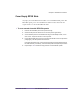
Amosphere NPM Installation Procedures (WCS) Install the GPS Antennas This procedure describes how to install two Zyfer GPS antennas on top of 1inch-diameter, hollow pipes using the supplied hardware. Consult your E1 package for any site-specific GPS antenna installation requirements. The NPM uses two GPS antennas for redundancy purposes—they do not affect each other’s operation and they can be installed in close proximity to each other. Figure 4.20 shows the Zyfer GPS antenna assembly.
Chapter 4: Installation Procedures Before You Begin Before you begin to install the GPS antennas: Select an installation location away from any objects that might obstruct satellite visibility to 10° of the horizon. Obstructions may cause a degradation of the GPS clock module’s performance. Ensure that the type and length of cabling used to connect the GPS antenna to the GPS clock module meets your attenuation and shielding requirements.
Amosphere NPM Installation Procedures (WCS) Install the Main and Diversity Antennas This procedure describes the general process for installing the main and diversity antennas. Consult your E1 package for any site-specific antenna installation requirements. Figure 4.21 shows the configuration of the main or diversity antenna).
Chapter 4: Installation Procedures To install the main and diversity antennas 1 Verify that you have the right type of antennas, both in terms of frequency and direction. 2 Run the antenna cable from the NPM racks to the intended location of each antenna. See your E1 package and installation MOP for antenna cable specifics. N O T E : Ensure that the cable remains clear of any sources of potential interference, such as transmitting equipment or power lines.
Amosphere NPM Installation Procedures (WCS) to 17 foot-pounds and ensure each connector is properly weatherproofed. ! 114 C A U T I O N : Do not over-tighten connectors. Overtightening the connectors may damage the cable and degrade the RF signal. iv Connect the BTS port on each bias tee to the ANT port on each RFSS module. The ANT port is located on the rear side of the RFSS module. v Connect the CIN port (also called Vout) on the rear side of the RFSS module to the DC port on the bias tee.
Chapter 5 POWER-ON PROCEDURES Chapter 5 This chapter provides step-by-step procedures for powering on the NPM and verifying basic functionality. Contents Power On the NPM ................................................................................................
Amosphere NPM Installation Procedures (WCS) Power On the NPM The power for the NPM is controlled by circuit breakers in the PDP, located at the top of each rack. Each power supply, RFSS module, cooling unit, and GPS clock module has its own circuit breaker, which means it can be powered on and off independently of the other devices. To power on the NPM 1 Ensure that your main +24V DC power supply is powered on and is providing a power source that meets the electrical requirements listed on page 27.
Chapter 5: Power-On Procedures Power Supply Circuit Breaker Bottom radio shelf, left power supply (slots 0–1) Radio rack PDP, CB 02 Bottom radio shelf, middle power supply (slots 2–3) Radio rack PDP, CB 03 Bottom radio shelf, right power supply (slots 4–5) Radio rack PDP, CB 04 Middle radio shelf, left power supply (slots 0–1) Radio rack PDP, CB 05 Middle radio shelf, middle power supply (slots 2–3) Radio rack PDP, CB 06 Middle radio shelf, right power supply (slots 4–5) Radio rack PDP, CB 07
Amosphere NPM Installation Procedures (WCS) RFSS Module Circuit Breaker RF shelf 0, RFSS module 0 RF rack PDP, CB 02 RF shelf 0, RFSS module 1 RF rack PDP, CB 03 RF shelf 0, RFSS module 2 RF rack PDP, CB 04 RF shelf 0, RFSS module 3 RF rack PDP, CB 05 RF shelf 1, RFSS module 0 RF rack PDP, CB 06 RF shelf 1, RFSS module 1 RF rack PDP, CB 07 RF shelf 1, RFSS module 2 RF rack PDP, CB 08 RF shelf 1, RFSS module 3 RF rack PDP, CB 09 RF shelf 2, RFSS module 0 RF rack PDP, CB 10 RF shelf 2, RF
Chapter 6 ON -SITE SOFTWARE INSTALLATION AND CONFIGURATION P ROCEDURES Chapter 6 This chapter describes how to optimize the individual cards in the NPM and explains the remaining steps required to make the NPM fully operation. Contents Optimize the GPS Clock Module ........................................................................... 120 Configure the Ethernet Switches ........................................................................... 122 Post-Installation Activities ......................
Amosphere NPM Installation Procedures (WCS) Optimize the GPS Clock Module To ensure accurate timing, you must optimize the operation of the GPS clock module. Optimizing the operation of the GPS clock module involves compensating for the signal delay caused by the length of the GPS antenna wiring. Consult with your cable manufacturer for the delay characteristics of your cable type. You need to express the delay values in nanoseconds per meter (ns/m).
Chapter 6: On-Site Software Installation and Configuration Procedures To optimize the GPS clock module 1 Connect a PC to the GPS clock module using a custom adapter and a standard serial cable. N O T E : Using a standard serial or null modem cable without a custom adapter will not work. 2 Start a serial terminal session using the settings shown in Table 6.1.
Amosphere NPM Installation Procedures (WCS) Configure the Ethernet Switches In order to operate in the NPM, the Ethernet switches require custom settings. You need to configure the Ethernet switches only once; the configuration is stored in the switch’s nonvolatile memory. You can connect to the Ethernet switch by connecting a custom serial cable with a null modem adapter to the console port located on the front panel. Figure 6.1 shows the connections for the Ethernet switch serial cable.
Chapter 6: On-Site Software Installation and Configuration Procedures To configure the Ethernet switches 1 Establish a serial connection with the Ethernet switch: i Connect a PC to the Ethernet switch using the supplied RJ-11 to DB-9 serial cable with a null modem adapter. See Table 6.2 for pin assignments. ii Start a serial terminal session using the settings shown in Table 6.3. Parameter Setting Baud 9600 bits/s Data bits 8 Parity None Stop bits 1 Flow control None Table 6.
Amosphere NPM Installation Procedures (WCS) save ↵ save ↵ where: switch_name is either sw0 or sw1 switch_ip_address is the IP address of the Ethernet switch router0-0_ip_address is the IP address of the primary router 6 Reboot the Ethernet switch by typing: switch reset ↵ 7 124 Repeat steps 1 to 6 for the other Ethernet switch.
Chapter 6: On-Site Software Installation and Configuration Procedures Post-Installation Activities After the installation of the NPM is complete, the following steps may be required in order to make the NPM fully functional: Upgrade the NPM software – Amosphere NPM software is typically pre-installed at the factory. It may be necessary to upgrade the software to achieve full functionality. See the Amosphere OAMP Guide for information about installing new software loads.
Amosphere NPM Installation Procedures (WCS) 126 Part 003609A revision 01 December 16, 2002
Appendix A NPM DECOMMISSIONING Chapter A This chapter describes how to safely take an NPM out of service. Contents Decommissioning an NPM .....................................................................................
Amosphere NPM Installation Procedures (WCS) Decommissioning an NPM Decommissioning occurs whenever an NPM is taken out of service or moved to a new location. W A R N I N G : Ensure that the necessary requirements and procedures have been reviewed prior to the start of any power-related activity. Refer to your power cut-over MOP for procedures specific to your site.
LIST OF ABBREVIATIONS Abbreviation Expansion AH application host AWG American wire gauge BTU British thermal unit CFM cubic feet per minute CSU customer service unit dB decibel DIV diversity ES Ethernet switch GPS Global Positioning System IP Internet Protocol modem modulator–demodulator MOP methods of procedure NC not connected NEBS network equipment-building system NOC network operations center NPM Network Port Manager OAMP operations, administration, maintenance, and pr
Amosphere NPM Installation Procedures (WCS) Abbreviation Expansion RSC radio sector controller RX receive TX transmit UBC utility bus controller WCS wireless communications services 130 Part 003609A revision 01 December 16, 2002
GLOSSARY A In the SOMA Networks implementation, backhaul refers to the wireline link between the NPM and the network core. air interface The standards governing radio transmission between two elements of a wireless system, such as an NPM and a SOMAport.
Amosphere NPM Installation Procedures (WCS) divides a geographic area into cells, each of which has its own radio transmitters and receivers. Competing digital cellular systems include GSM and CDMA. central office A physical voice and data switching center, also called the local exchange, where local loops are connected to the core network. CompactPCI An open, industy-standard architecture based on the PCI architecture. Electrically, CompactPCI is superset of PCI.
Glossary L N LAN (local area network) network core A network of computers, workstations, printers, file servers, and other devices that serves a particular group of users and is usually confined to a small geographical area, such as a building or campus. In a SOMA Networks context, the network core is the switching fabric that interconnects all components and transfers bearer traffic, signaling information, embedded control messages, and network management traffic.
Amosphere NPM Installation Procedures (WCS) R Switches operate at the data link layer of the OSI Reference Model. RF (radio frequency) Any frequency in the electromagnetic spectrum that is used for radio transmission (typically 1 MHz to 300 GHz). RJ-45 (registered jack-45) An 8-wire connector used to connect computers to an Ethernet or a token-ring LAN. router A device that forwards packets of any type from one LAN or WAN to another.
I NDEX A adapter GPS serial interface, 120 airflow requirements, 26 for cards, 91 for occupied radio bays, 75 alarm cables connecting, 100 aligning racks. See racks altitude requirements, 26 anchor bolts, 56 securing racks with, 59–60 antennas, 35 installing, 109 GPS, 110–111 main and diversity, 112–114 antistatic.
Amosphere NPM Installation Procedures (WCS) tools, 42 circuit boards precautions when handling, 41 circuit breakers, 61, 116 in radio and utility shelves, 88, 117 in RFSS modules, 118 maximum loading in PDP, 29 clock module. See GPS clock module CompactPCI cards. See cards CompactPCI power supplies.
Index size and torque values, 24 filler panels location in rack, 73 to cover empty card slots, 91 to cover empty RFSS slots, 79 fuses replacing in PDP, 30 GPS clock module, 77 racks, 55 positioning and aligning, 58 preparing location, 56 securing, 59–60 See also attaching and inserting Internet gateway, 33 inventory checking. See checklists G gateways Internet, 33 PSTN, 33 global positioning system clock. See GPS clock module GPS antennas, 103 assembly, 110 installing, 111 GPS clock module antennas.
Amosphere NPM Installation Procedures (WCS) P R parameter settings Ethernet switch, 123 GPS clock module, 121 part numbers cables, 93 PDP power, 96–97 cards, 82–85 PDP circuit breakers, 29 grounding point for wrist straps, 41 power cables. See power cables rear cover attachment, 61 replacing fuses in, 30 weight, 23 physical requirements for moving NPMs, 23 space, 22 positioning racks. See racks power cables, 94 connecting, 65–66, 96–97 power distribution panel.
Index antenna configuration, 112 circuit breakers, 118 connecting antennas to, 112–114 inserting into RF rack, 78 location in RF rack, 73 powering on, 117–118 weight, 23 RFSS signal cables. See signal cables RFSS slots. See filler panels routers, 33 Sunset OCx, 43 supplies.
Amosphere NPM Installation Procedures (WCS) 140 Part 003609A revision 01 December 16, 2002