
User Manual


December 16, 2002 Part 003609A revision 01 67
Chapter 4: Installation Procedures
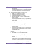
Test Power Supply Voltage and Ground
This procedure tests the voltage levels and grounds of the NPM and the main
power supply. The test ensures that the main power supply is providing +24V
DC and that the power supply and NPM are properly grounded.
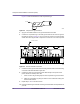
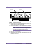
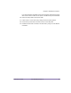
Figure 4.8 shows the pins of the NPM power cables.
Figure 4.8
Power Cable Pins
To test the power supply voltage and ground
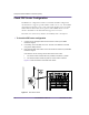
1 Ensure that all NPM circuit breakers (CB) are in the OFF (down) position.
2 Remove the three fuses from the PDP on the radio rack by using a 1/4-inch
flathead screwdriver.
3 Configure your multimeter to read DC voltage. Autoscaling may be used.
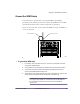
4 If the NPM has a pre-installed utility shelf, disconnect the CB 11 power cable from
the PS0 connector on utility shelf. Leave the power cable connected to CB 11
connector.
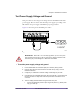
5 Test the voltage potential between the ground and return pins:
i Connect the multimeter probes to pins A2 (ground) and A3 (–). Either probe
may go to either pin.
00427
+
GND
-
A3A2A1
A1 - +24V to +28V DC
A2 - chassis ground
A3 - negative return
WARNING: When CB 11 is in the ON (up) position, pin A1 is hot (+24V
DC). Never short-circuit pin A1 with any other pins or objects. Failure to heed
this warning may cause damage to or destruction of the NPM.