
User Manual

December 16, 2002 Part 003609A revision 01 49
Chapter 3: Pre-Installation Activities
Configure Controller Cards
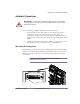
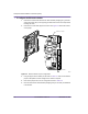
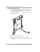
It may be necessary to modify the configuration switches on the utility bus
controllers and radio sector controllers. The cards are identical and have the same
configuration. The NPM uses a configuration of these cards that differs from the
manufacturer’s original settings.
NOTE: If the controller cards are pre-installed in the shelves,
then they have already been configured and this procedure is not
required.
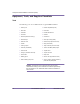
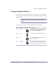
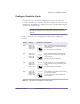
Table 3.6 shows the correct settings of the controller cards’ configuration
switches.
Switch Setting Appearance Description
SW3 SW3-1: ON
SW3-2: OFF
SW3-3: OFF
SW3-4: OFF
SW3-1 and SW3-2 enable battery-backup of the
CMOS memory. SW3-1 must be left ON; SW3-2
must be left OFF.
The other switches must be left OFF.
SW4 SW4-1: OFF
SW4-2: OFF
SW4-3: ON
SW4-4: ON
SW4-1 and SW4-2 route Ethernet channels to
the location set in the BIOS. These switches
must be left OFF.
The other switches must be left ON.
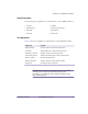
SW5 SW5-1: ON
SW5-2: OFF
SW5-3: OFF
SW5-4: OFF
SW5-1 causes the card to boot its BIOS from
the on-board flash memory. This switch must be
left ON.
The other switches must be left OFF.
SW6 SW6-1: ON
SW6-2: OFF
SW6-3: OFF
SW6-4: OFF
SW6-1 enables console redirection for the serial
port and must be left ON.
The other switches are software-defined and
must be left OFF.
Table 3.6
Controller Card Configuration Switch Settings
Closed (ON)
1234
Open (OFF)
Closed (ON)
Open (OFF)
1234
Closed (ON)
1234
Open (OFF)
Closed (ON)
1234
Open (OFF)